Rotary worktable with self-locking function

A rotary table, self-locking technology, applied in the direction of the table, manufacturing tools, etc., can solve the problems of the table can not be rotated, reduce production efficiency, large area, etc., to facilitate workers to manually rotate the table, easy transportation and installation, Taking into account the effect of economic benefits

Inactive Publication Date: 2018-09-14
HENAN UNIV OF SCI & TECH
View PDF6 Cites 2 Cited by
  • Summary
  • Abstract
  • Description
  • Claims
  • Application Information

AI Technical Summary

Problems solved by technology

[0002] With the development of mechanization and automation technology in modern industry, the demand for manual work has been gradually reduced. However, there is no suitable mechanized equipment to replace the fitter work such as scribing and scraping. Some precision templates, molds, measuring tools and The matching surface still needs to rely on the craftsmanship of workers for precision machining. At the same time, in modern production, the inspection and measurement of parts, the cleaning and polishing of parts details, and printing marks are still dependent on manual labor.
[0003] The workbench is an indispensable device for placing parts during manual operations. When the existing workbench is installed on the ground, it is inconvenient for the worker to walk around the workbench when the worker is working. Reduce production efficiency; the existing workbench usually has a large area, and the distance between the two ends of the workbench is generally several meters. A batch of small and medium-sized parts weighing no more than an adult are placed on the workbench for manual processing in batches. This is a modern industrial production process. A production mode commonly used for economic benefits. In this case, when the part needs to be rotated to work on the part away from the edge of the workbench, the common method is that the worker drags the part through the wire rope, but the finished part is Dragging will damage the processed surface, so workers often need to stand on the workbench and operate in a bent or crouched state, which completely deviates from the original intention of placing parts on the workbench for manual operation, and is extremely inconvenient to use , Precision operations such as inspection and measurement of parts have caused great difficulties and low production efficiency
[0004] The main reason for the above problems is that the table cannot be rotated. In the existing industrial production, although the rotary table is widely used in various large and medium-sized machine tools, especially in CNC machine tools, the rotary table used in the machine tool together with the power unit It is obviously not economical and impractical to transfer to manual work together with the electronic control system. Therefore, providing a rotary table with simple structure, low cost and easy use will bring convenience and improve manual work. It is of great significance to take into account the economic benefits while production efficiency

Method used


Image

  • Rotary worktable with self-locking function
  • Rotary worktable with self-locking function
  • Rotary worktable with self-locking function

Examples


Embodiment 1

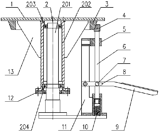
[0020] see figure 1 , 2 , 4. A rotary table with self-locking function, including a shaft 201 vertically installed on the base, a sleeve 202 is sleeved on the outer circumference of the shaft 201, and the axis centers of the sleeve 202 and the shaft 201 coincide and pass through The upper bearing 203 and the lower bearing 204 are supported and positioned, and the end of the sleeve 202 away from the base is equipped with a turntable plate 1 for placing parts, and the other end of the sleeve 202 is equipped with a sleeve end cover 12 to facilitate sealing and positioning; the turntable plate 1 It is a circular plate and the axis of the circular plate coincides with the axis of the sleeve 202 and the shaft 201. There are several lifting holes 14 on the upper end surface of the turntable plate 1, and several spaced holes are arranged on the outer circumference of the turntable plate 1. The handrail 15 is in order to manually rotate the turntable plate 1, and several reinforcing r...

Embodiment 2

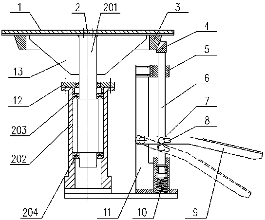
[0022] see image 3 , a rotary table with self-locking function, the difference from Embodiment 1 is that the sleeve 202 is installed vertically on the base, the shaft 201 is passed through the sleeve 202 and passes through the upper bearing 203 and the lower bearing 204 Supporting positioning, the turntable plate 1 is installed on the end of the shaft 201 away from the base, several reinforcing ribs 13 are installed between the bottom of the turntable plate 1 and the shaft 201, and the rest are the same as in the first embodiment.


PUM


Abstract

The invention discloses a rotary worktable with a self-locking function. The rotary worktable with the self-locking function comprises a rotary table plate arranged on a rotary mechanism. A conical guide ring is arranged at the bottom of the rotary table plate. The rotary table with the self-locking function further comprises a plug-pin with a conical guide block at the end of the plug-pin. A plug-pin seat is connected to the other end of the plug-pin through a spring. The spring is used for jacking the plug-pin to enable the conical surfaces of the conical guide block and the conical guide ring to be attached tightly to achieve the self locking of the rotary worktable. A footplate is hinged to the plug-pin seat. A sliding groove is formed in the footplate. A positioning block is installedon the plug-pin. The one end away from the plug-pin, of the positioning block is arranged in the sliding groove in a penetrating mode. The footplate is driven to move in the direction of a base to enable the positioning block to slide in the sliding groove and to drive the plug-pin to move in the direction of the plug-pin seat, so that the conical surfaces of the conical guide block and the conical guide ring are separated to facilitate the free rotation of the rotary table plate, the structure is simple, the cost is low, the problems that a worker walks around the worktable and stands on theworktable for manual operation are avoided, the use is convenient, convenience is brought for the manual operation, the production efficiency is improved while the economic benefit is achieved.

Description

technical field [0001] The invention relates to the field of rotary worktables, in particular to a rotary worktable with a self-locking function. Background technique [0002] With the development of mechanization and automation technology in modern industry, the demand for manual work has been gradually reduced. However, there is no suitable mechanized equipment to replace the fitter work such as scribing and scraping. Some precision templates, molds, measuring tools and The matching surface still needs to rely on the craftsmanship of workers for precision machining. At the same time, in modern production, the inspection and measurement of parts, the cleaning and polishing of parts details, and printing and marking are still dependent on labor. [0003] The workbench is an indispensable device for placing parts during manual operations. When the existing workbench is installed on the ground, it is inconvenient for the worker to walk around the workbench when the worker is w...

Claims


Application Information

Patent Timeline
IPC IPC(8): B25H1/14
CPCB25H1/14
Inventor 张志红谢金法岳菊梅谢晓琳马浩霖
Owner HENAN UNIV OF SCI & TECH
Why Eureka
Try Eureka