Supercharge Your Innovation With Domain-Expert AI Agents!

Combined test device and method for treating wastewater by means of hot-air concentration-flash evaporation

A technology for treating waste water and hot air, which is applied in the direction of heating water/sewage treatment, special treatment targets, water/sewage treatment, etc. It can solve the problems of pipeline scaling, high operating cost of evaporation technology, blockage, etc. The effect of simple, simple test equipment

Pending Publication Date: 2018-09-14
南京常荣环境科技有限公司 +2
View PDF6 Cites 1 Cited by
  • Summary
  • Abstract
  • Description
  • Claims
  • Application Information

AI Technical Summary

Problems solved by technology

[0005] The present invention finally realizes the zero discharge of waste water by making full use of the heat of the hot air, and at the same time combines the high-sonic-intensity sonic descaling technology, thereby solving the problems of high operating costs of the existing evaporation technology, scaling and blockage of pipelines in the evaporation process, etc.

Method used


Image

  • Combined test device and method for treating wastewater by means of hot-air concentration-flash evaporation
  • Combined test device and method for treating wastewater by means of hot-air concentration-flash evaporation
  • Combined test device and method for treating wastewater by means of hot-air concentration-flash evaporation

Examples


Embodiment 1

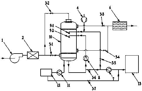
[0035] Such as figure 1 Shown is a schematic diagram of a device for treating waste water using hot air concentration-flash evaporation provided in this embodiment, including a fan 1, an air heater 2, a demister 6, a water supply pump 7, a concentrated flash tank 10, an outlet pump 11, a collection Tank 12 and raw water buffer tank 13, wherein fan 1 is connected to air heater 2, and air heater 2 is connected to concentrated flash tank 10, and the air outlet of concentrated flash tank 10 is connected to demister 6; The outlet is connected to the collection tank 12 through the outlet pump 11; the collection tank 12 is connected to the water supply pump 7; the raw water buffer tank 13 is connected to the water supply pump 7; the water supply pump 7 is connected to the liquid inlet of the concentrated flash tank 10 through a pipeline.

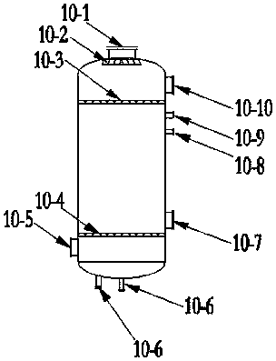
[0036] figure 2 As shown, it is a schematic diagram of the concentration flash tank, including the first air inlet 10-1 arranged on the top of t...

Embodiment 2

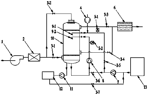
[0038] Embodiment 2 This embodiment is a further improvement on the basis of Embodiment 1, wherein as image 3 As shown, the fifth pipeline is provided with a first sonic descaler 5-1, and the sixth pipeline is provided with a second sonic descaler 5-2, as Figure 4 As shown, the first air distributor 10-3 and the second air distributor 10-4 are gas distribution plates with uniformly arranged holes.

[0039] The method of using the hot air concentration-flashing device for treating wastewater provided by this embodiment to carry out concentration and flash treatment specifically includes the following steps:

[0040] Step 1, waste water concentration: The waste water is transported to the sonic single-phase flow atomization nozzle under the action of the circulating pump and atomized into small droplets in the concentration flash tank, and the air at normal temperature and pressure enters the air heater under the action of the fan. Internally heated to high-temperature and hi...

Embodiment 3

[0043] Utilize the device that utilizes hot air concentration-flashing treatment waste water provided by the present invention to carry out the method for concentration and flash treatment, the specific process is as follows:

[0044] Wastewater concentration: the high-salt wastewater in the raw water buffer tank enters the circulation pipeline through the pipeline connected with the sixth valve under the delivery of the water supply pump, and enters the sonic single-phase flow atomization nozzle under the operation of the circulation pump, and the liquid is atomized into Small droplets, the liquid particle size is 200μm-2000μm. The air at normal temperature and pressure enters the air heater under the conveyance of the fan and becomes high-temperature hot air. The temperature of the hot air is 80-110°C. The high-temperature gas enters the concentrated flash tank through the second air inlet through the pipeline connected with the first valve. The liquid droplets contact and e...


PUM


Abstract

The invention discloses a device and a method for treating wastewater by means of hot-air concentration-flash evaporation. The device comprises a fan, an air heater, a mist eliminator, a water supplypump, a concentration and flash evaporation tank, a water outlet pump, a collecting tank and a wastewater buffer tank. The fan is connected with the air heater, the air heater is connected with the concentration and flash evaporation tank, and the concentration and flash evaporation tank is connected with the mist eliminator; a concentrated liquid outlet of the concentration and flash evaporationtank is connected with the collecting tank; the collecting tank is connected with the water supply pump; the water supply pump is connected with a liquid inlet of the concentration and flash evaporation tank. The method includes forming hot air by the aid of the fan and the air heater, forming mist drop in the concentration and flash evaporation tank by the wastewater in mist spray forms and concentrating liquid by means of convection heat exchange between the hot air and the mist drop; forming mist drop by concentrated liquid in the concentration and flash evaporation tank by the aid of an acoustic two-phase flow atomizing nozzle and carrying out flash evaporation by the aid of hot air. The wastewater for forming the mist drop in the concentration and flash evaporation tank in the mist spray forms is pumped into the concentration and flash evaporation tank by the water supply pump. The device and the method have the advantages that devices can cooperate with one another in the same system, accordingly, concentration operation and flash evaporation operation can be independently carried out, and process control and program monitoring can be facilitated.

Description

technical field [0001] The invention relates to a combined test device and method for treating waste water by using hot air concentration-flash evaporation, which belongs to the key equipment and method in the technical field of waste water concentration reduction and high-salt waste water zero-discharge treatment. Background technique [0002] The existing evaporative concentration technology mostly adopts two forms of multi-effect evaporation or mechanical vapor recompression. There are many defects in these process equipments in actual operation: (1) The main heat source of multi-effect evaporation is steam, which consumes a lot of energy to process tons of water, the process is complicated, and the system maintains a lot. The mechanical vapor recompression evaporation system mainly uses a steam compressor to complete the recompression of the steam at the cost of power consumption and finally use it as a heat source for the evaporation of waste water. The energy consumpti...

Claims


Application Information

Patent Timeline
Patent Type & Authority Applications(China)
IPC IPC(8): C02F1/06
CPCC02F1/06C02F2303/14C02F2201/007
Inventor 顾承真闻小明张玲丽张荣初邹怡然李淼
Owner 南京常荣环境科技有限公司
Features
  • R&D
  • Intellectual Property
  • Life Sciences
  • Materials
  • Tech Scout
  • Unparalleled Data Quality
  • Higher Quality Content
  • 60% Fewer Hallucinations
Learn More