
A dual ion beam metal coating automation equipment

An automated equipment, metal coating technology, applied in the direction of ion implantation coating, metal material coating process, sputtering coating, etc., can solve the problems of reducing the service life of the device, the influence of the device, and the inability to achieve the cooling effect, and achieve improvement. Combined strength, improved heat dissipation protection, and reasonable structure

Active Publication Date: 2018-11-06
广东英冠薄膜科技有限公司
View PDF8 Cites 0 Cited by
  • Summary
  • Abstract
  • Description
  • Claims
  • Application Information

AI Technical Summary

Problems solved by technology

[0005] The purpose of the present invention is to provide a kind of double ion beam metal coating automation equipment, to solve the problem that the main ion source, auxiliary ion source and deposition target installation position of the above-mentioned device are fixed, the ion incidence angle cannot be greatly adjusted, and no rotation work is given. Due to the specific installation method of the table, the device can only coat the entire surface of the workpiece with a small shape. When the shape of the workpiece is large, or the shape is not flat but irregular, the film layer is difficult to cover the entire surface, and it is easy to appear uniform film. At the same time, neither the main ion source nor the auxiliary ion source of the above-mentioned device has a specific cooling scheme, which cannot achieve a good cooling effect. Working at a high temperature for a long time will easily affect the device and reduce the use of the device. The problem of longevity

Method used


Image

  • A dual ion beam metal coating automation equipment
  • A dual ion beam metal coating automation equipment
  • A dual ion beam metal coating automation equipment

Examples


Embodiment 1

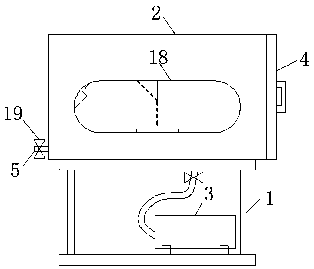
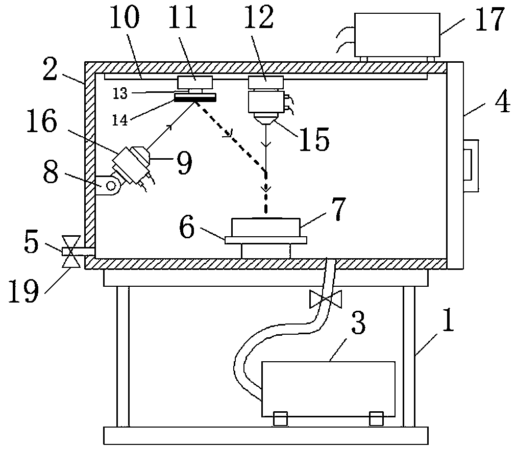
[0026] Preferred embodiment one of the present invention, such as Figure 1~3As shown, the present invention provides a kind of technical scheme: a kind of double ion beam metal coating automation equipment, comprises equipment frame 1, and the top of equipment frame 1 is provided with vacuum coating chamber 2, and the front side wall of vacuum coating chamber 2 is provided with Observation window 18, in order to observe the working situation in the vacuum coating chamber 2, the bottom of the inner chamber of the equipment frame 1 is provided with a vacuum device 3, the vacuum device 3 is connected with the vacuum coating chamber 2, and the right side wall of the vacuum coating chamber 2 is arranged There is a sealed door body 4, the left side wall bottom of the vacuum coating chamber 2 is provided with an air inlet 5, and the connecting pipe between the vacuum device 3 and the vacuum coating chamber 2 and the air inlet 5 are all provided with a valve 19 to control the air flow...

Embodiment 2

[0032] Embodiment 2 When adjusting the target slider 11 and the auxiliary source slider 12, the expansion and contraction of the electric adjustment devices 2024 on both sides can make the corresponding adjustment device 202 have a displacement change in the vertical direction. In theory, as long as the adjustment device 202 is in the The displacement length in the vertical direction is sufficient, and the translation adjustment device 203 as a whole can perform a large swing, with left high and right low or left low and right high, and at the same time, the driving of the electric reel 2032 can synchronously adjust the target slider 11 and the auxiliary source slider 12, this structure is especially suitable for the case where there is a large area of ​​arc in the special-shaped processing surface, which can significantly improve the quality of processing.

[0033] Such as Figure 6 In the third preferred embodiment of the present invention, the linear guide rail 10 in the fi...

Embodiment 3

[0035] Embodiment 3 When adjusting the target slider 11 and the auxiliary source slider 12, the distance between the target slider 11 and the auxiliary source slider 12 in the horizontal direction can be adjusted, and both can be rotated at the same time. Considering the improvement of the rotation adjustment Angle, to avoid the rest of the workpiece, also considering the cost reduction and the complexity of the industrial control adjustment system, directly on the adjustment seat 211 is provided with a fine-tuning slider 2111 that can be ejected in a straight line, which is more convenient in control and basically It can play the role of the universal device, and the third embodiment is more suitable for irregular surfaces to be processed.


PUM


Abstract

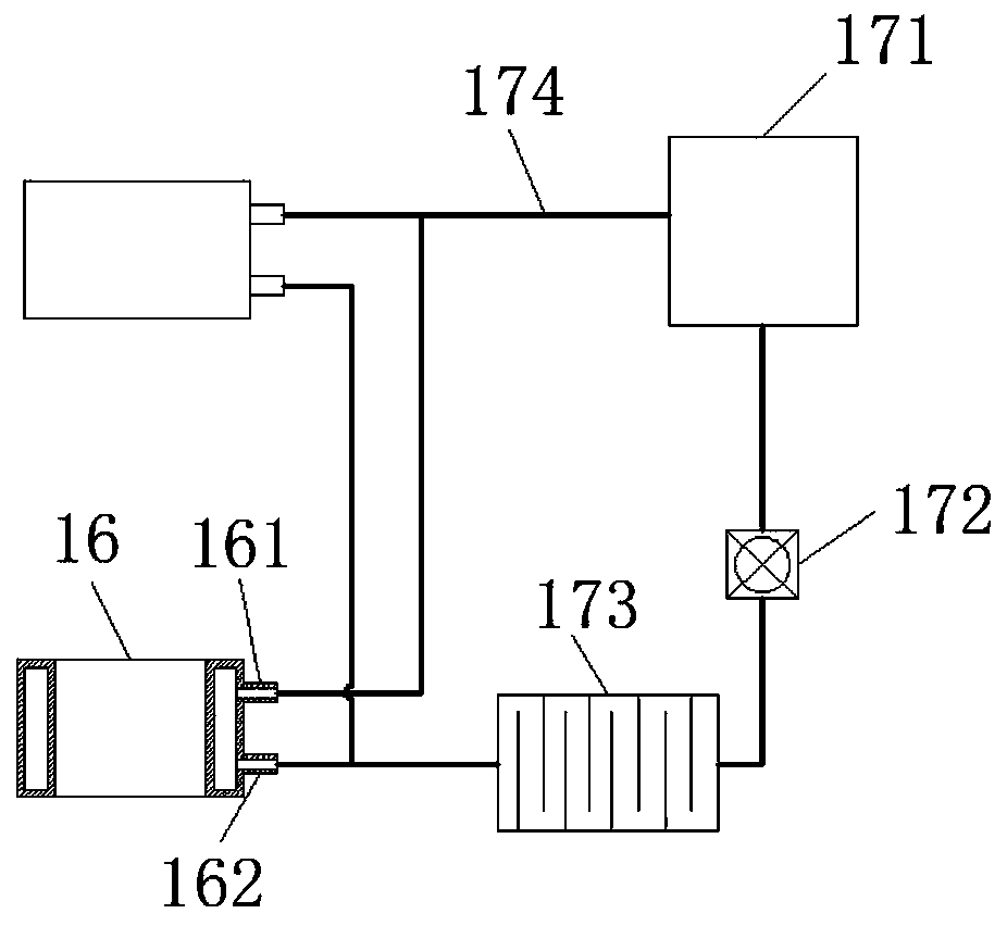
The invention relates to double-ion-beam metal coating automation equipment. A vacuum coating chamber is arranged at the top of an equipment rack; a main ion source is arranged in the middle of the left side wall of an inner cavity of the vacuum coating chamber; a target material sliding block and an auxiliary source sliding block are arranged at the top of the inner cavity of the vacuum coating chamber separately, the target material sliding block is always located on the left side of the auxiliary source sliding block, the target material sliding block and the auxiliary source sliding blockcan move back and forth along the same horizontal line, a target material is arranged on the target material sliding block, and an auxiliary ion source is fixedly installed at the bottom of the auxiliary source sliding block; cooling wrapping layers are arranged on the outer walls of the main ion source and the auxiliary ion source respectively. The double-ion-beam metal coating automation equipment has the advantages that through heat dissipation protection, the service life of the equipment can be prolonged, and the use effect of the equipment can be improved; besides, the equipment can adapt to coating with various forms and sizes through various adjustment modes.

Description

technical field [0001] The invention relates to the technical field of ion coating, in particular to a double ion beam metal coating automatic equipment. Background technique [0002] In the known technical field, ion beam sputtering coating technology provides new technology and new technology of thin film coating for scientific research and production, and it is a new technology for superalloy conductor thin film, magnetic thin film device, thin film integrated circuit, thin film sensor, optical thin film, metal The wide range of applications such as heterostructure thin film preparation and thin film preparation in material modification provide new technical means. With the continuous expansion and extension of the application field of ion beam coating technology, the requirements for ion beam sputtering deposition thin film equipment are getting higher and higher. However, at present, this type of equipment is still dominated by single-function ion beam sputtering coati...

Claims


Application Information

Patent Timeline
Patent Type & Authority Patents(China)
IPC IPC(8): C23C14/34
CPCC23C14/34
Inventor 曹云娟
Owner 广东英冠薄膜科技有限公司
Learn More