Method and system for increasing energy storage efficiency of compressed air by using ORC

A compressed air energy storage and high-pressure air technology, which is applied in steam engine devices, machines/engines, mechanical equipment, etc., can solve problems such as unsuitable applications, constraints, and low energy storage efficiency, so as to avoid heat loss, increase power generation, and Effect of Energy Storage Efficiency Improvement

Inactive Publication Date: 2018-09-14
NORTH CHINA ELECTRIC POWER UNIV (BAODING)
View PDF5 Cites 10 Cited by
  • Summary
  • Abstract
  • Description
  • Claims
  • Application Information

AI Technical Summary

Problems solved by technology

However, this liquid compressed air energy storage system adds an air liquefaction link and a liquid pump, making the energy storage efficiency of the liquid compressed air energy storage system lower than that of the general gaseous compressed air energy storage system
Therefore, the energy storage efficiency of the LAES system is the main factor limiting its development. Although the efficiency of the AA-CAES system is higher than that of the LAES system, it is also restricted by efficiency factors.
[0005] Chinese patent CN105569753A discloses an organic Rankine cycle power generation device using waste heat in the process, but this device only uses the waste heat in the energy release process to heat the organic working fluid for power generation, because the temperature of the waste heat in the energy release process is about 50 degrees, so The ORC power generation efficiency of this device is not high, considering the cost issue, this device is not suitable for application

Method used


Image

  • Method and system for increasing energy storage efficiency of compressed air by using ORC
  • Method and system for increasing energy storage efficiency of compressed air by using ORC

Examples


Embodiment Construction

[0023] The embodiments will be described in detail below in conjunction with the accompanying drawings.

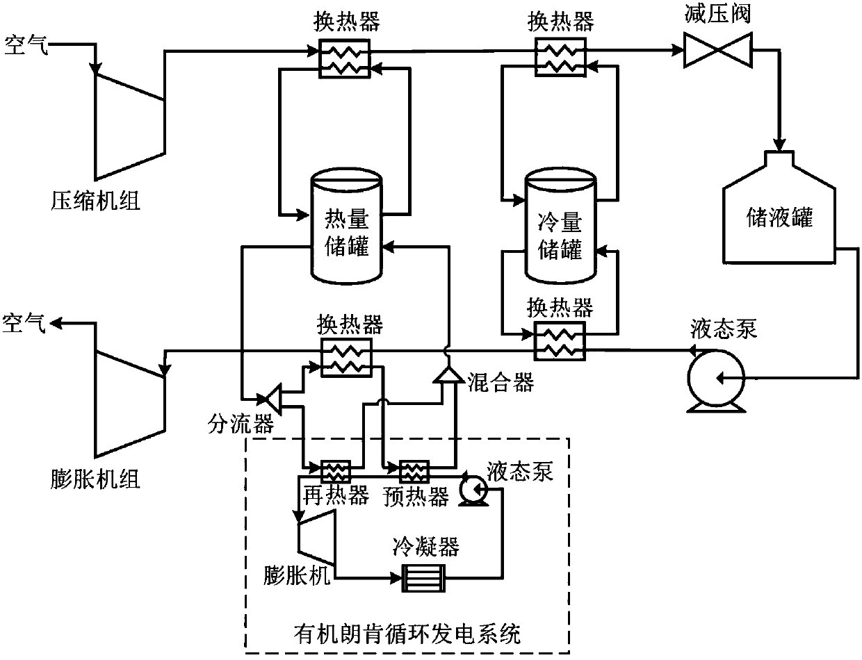
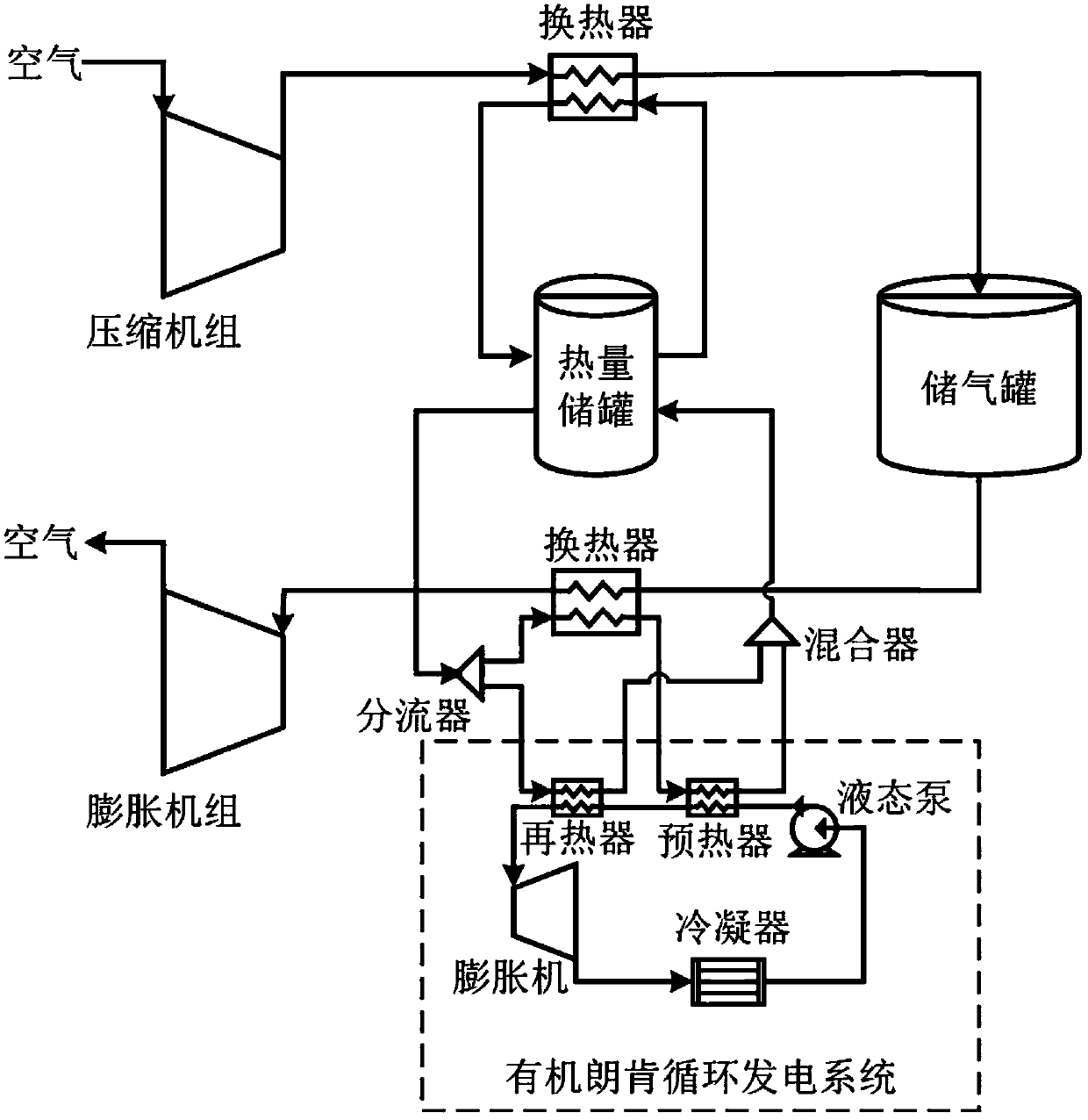
[0024] The present invention is a method for improving the efficiency of the compressed air energy storage system by coupling the ORC system with the CAES system. figure 1 It is the LAES system diagram of the coupling ORC of the present invention, figure 2 It is the AA-CAES system diagram coupled with ORC of the present invention. The method is described by taking the LAES system as an example, but the method is also applicable to the AA-CAES system.

[0025] By establishing the thermodynamic model of the LAES system, in the process of energy storage, the air is compressed and the compression heat is stored in the heat storage tank; in the process of energy release, the heat in the heat storage tank is used to heat the high-pressure air, and the heated Air enters the expander and expands to do work. Through calculation, it is found that when the air flow in the energy ...


PUM


Abstract

The invention belongs to the technical field of electric energy storage of compressed air, in particular to a method and system for increasing energy storage efficiency of compressed air by using ORC.The method comprises the following steps: during an energy storage process, compressing air and storing compression heat into a heat storage tank; during an energy releasing process, heating high-pressure air by a part of heat in the heat storage tank, wherein heated air enters an expansion machine to do work through expansion and the remaining heat of a heat storage working medium after an expansion process and the remaining partial heat in the heat storage tank are used for organic rankine cycle to generate electricity. The system comprises a compressor unit, a first heat exchanger, an airstorage tank, a second heat exchanger and an expansion unit. The first heat exchanger is connected with the heat storage tank. The heat storage tank is connected with the second heat exchanger and anorganic rankine cycle electricity-generating system. The remaining heat storage amount in a compressed air energy storage system is fully utilized. Firstly, the remaining heat is firstly used for pre-heating an organic working medium. Then, storage heat that cannot be fully used is used for reheating the working medium in order to ensure that heat is completely leveraged.

Description

technical field [0001] The invention belongs to the technical field of compressed air electric energy storage, and in particular relates to a method and a system for improving compressed air energy storage efficiency by using ORC. Background technique [0002] Compressed air energy storage (CAES) refers to the use of abundant power on the grid or unstable new energy power such as wind energy and solar energy to compress air when the electricity price is low, and seal and store the compressed high-pressure air. At this time, the high-pressure air is released and the air turbine is driven to drive the generator to generate electricity, so as to achieve the purpose of electric energy storage. In the existing compressed air energy storage system, the compressed high-pressure air is usually stored in an underground air storage room or an artificial air storage tank. [0003] The traditional CAES system needs to rely on the combustion chamber to provide heat energy to heat the hi...

Claims


Application Information

Patent Timeline
Patent Type & Authority Applications(China)
IPC IPC(8): F01K25/08F01K21/00F01K13/00F01K27/02F01K3/00
CPCF01K3/00F01K13/00F01K21/00F01K25/08F01K27/02
Inventor 何青王立健刘文毅杜冬梅
Owner NORTH CHINA ELECTRIC POWER UNIV (BAODING)
Why Eureka
Try Eureka