Mounting structure of full PCB mounting-type closed loop Hall current sensor

A technology of Hall current and installation structure, applied in voltage/current isolation, parts and instruments of electrical measuring instruments, etc. The effect of improving the ability of interference, reducing the size and volume, and widening the linear measurement range

Pending Publication Date: 2018-09-14
南京普肯传感科技有限公司
View PDF0 Cites 4 Cited by
  • Summary
  • Abstract
  • Description
  • Claims
  • Application Information

AI Technical Summary

Problems solved by technology

[0004] 1. Due to the small current ampere-turns of the full PCB-mounted open-loop Hall current sensor, in order to increase the current ampere-turns, the primary must be wound with multiple turns, that is, wound on a single air gap, single multi-layer punched annular core For making multi-turn coils, due to the small size of the magnetic core, it is time-consuming and troublesome to process large-scale winding; and in order to ensure the output amplitude of the sensor, the circuit amplification factor is large, and the zero point and amplitude of the sensor are repeatedly adjusted, making the open-loop Hall current Sensor production efficiency is too low for efficient high-volume production
Moreover, the magnetic circuit structure of this current sensor determines that the residual magnetism of the magnetic core is too large, which seriously affects the measurement accuracy of small currents. The measurement range is 3 times the rated current, the accuracy is preferably 1.5% FS, and the small signal bandwidth can only be Achieve 0-50KHZ
[0005] 2. Although the fully PCB-mounted closed-loop Hall current sensor uses a multi-layer punched-to-insert ring core structure and the primary and secondary coils are wound separately to achieve mass production, the lead-out end of the primary thick coil is not easy to install and fix accurately. Affect mass production efficiency; and the cross-section of the multi-layer punched ring core is square, coupled with the skeleton, the coil path is long, the internal resistance is large, the linear measurement range of the sensor is small, and the anti-saturation ability is poor; in order to reduce the coil internal Resistance, thicker wire diameter, not only increases the volume and weight of the sensor, is not conducive to the miniaturization of the sensor, but also consumes more copper, which increases the cost of the sensor. This structure does not fundamentally solve the remanence problem of the magnetic core, especially In many control systems, the power supply of the Hall current sensor lags behind the monitored current in time, that is, there is a monitoring current first and then the sensor power supply is added.
[0006] 3. Since the primary and secondary coils of the fully PCB-mounted closed-loop Hall current sensor are located on both sides of the magnetic core, they are installed and fixed on the PCB board with the pins on the skeleton after processing, and then installed into the shell, and the whole body is sealed with potting glue. For perfusion, the initial coil is completely sealed. When the current is large or the heat generated by the coil cannot be discharged, the temperature of the Hall current sensor shell rises sharply, and the zero point and amplitude temperature drift of the Hall current sensor are relatively large. , Seriously affect the measurement accuracy and environmental resistance of the Hall current sensor! It also limits the application field and versatility of the Hall current sensor!

Method used


Image

  • Mounting structure of full PCB mounting-type closed loop Hall current sensor
  • Mounting structure of full PCB mounting-type closed loop Hall current sensor
  • Mounting structure of full PCB mounting-type closed loop Hall current sensor

Examples


Embodiment

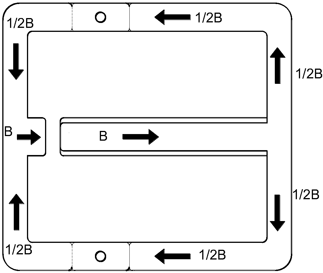
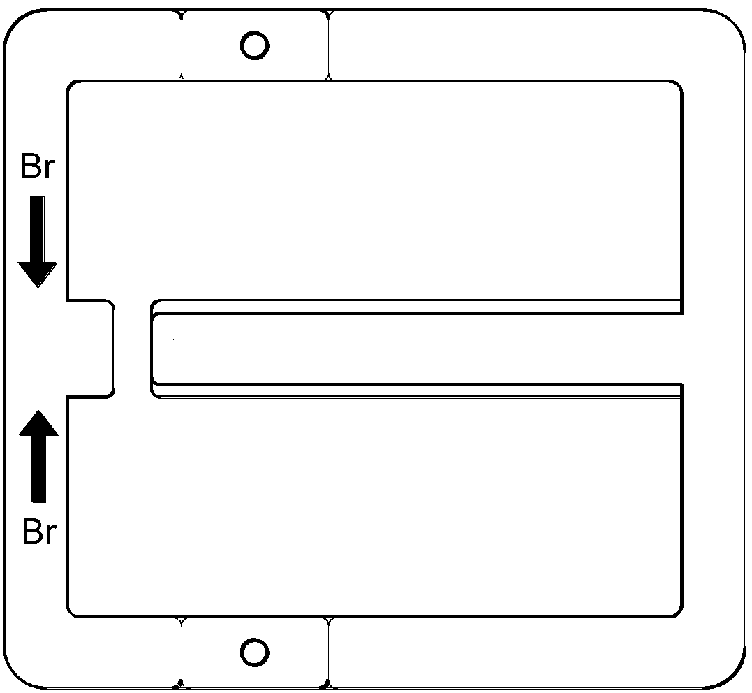
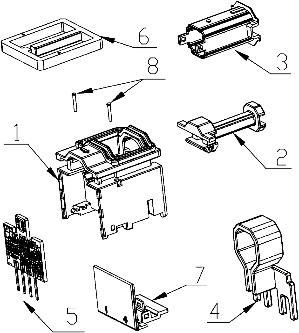
[0057] The installation structure of the fully PCB-mounted closed-loop Hall current sensor of this embodiment includes a housing and a cover plate when necessary, a magnetic core, two fixing pins, two skeletons and coil windings, and a PCB board. The skeleton and the cover plate, PCB board and magnetic core when necessary are installed on the shell. There is a secondary winding on the inner frame, and a primary winding on the outer frame. The inner and outer frames and the coil winding are located on the center column of the magnetic core; The air gap is located near the end of the central column of the magnetic core; there is a Hall element in the air gap, and the Hall element is a chip package; the window part of the Hall element on the PCB is inserted into the slot of the inner frame and connected to the air gap of the magnetic core Connected, the secondary winding is connected to the circuit on the PCB board.

[0058] The specific implementation steps are:

[0059] 1. Us...


PUM


Abstract

A mounting structure of a full PCB mounting-type closed loop Hall current sensor relates to the field of Hall current sensor mounting structure components. According to the invention, a magnetic core,a skeleton, a PCB are all mounted on a housing. An air gap is arranged near the tail end of a central post of the magnetic core. A sheet packaged Hall element is arranged in the air gap. The skeletonincludes an inner skeleton and an outer skeleton. A part of the PCB pasted with a window of the Hall element is inserted into a slot the inner skeleton and communicates with the air gap of the magnetic core. The secondary winding is connected with a circuit on the PCB. The housing is provided with mounting holes for the inner skeleton and the outer skeleton. The housing is provided with a pin mounting hole or slot used for mounting a primary winding. The housing is provided with a slot used for mounting and fixing the magnetic core and a fixing needle hole. The housing is provided with a clipused for mounting the PCB. According to the invention, aims of simple structure, mounting convenience, higher anti-interference capability and wider application range are achieved.

Description

technical field [0001] The invention relates to the field of Hall current sensor installation structure components, in particular to a full PCB installation type closed-loop Hall current sensor installation structure. Background technique [0002] Current sensor is a widely used electronic component, which is widely used in various current conversion technologies, AC numerical control devices and other automatic control fields where current is the control object. [0003] There are many methods for non-contact measurement and monitoring of current. Hall current sensors are widely used and industrialized because of their excellent cost performance; and full PCB-mounted closed-loop Hall current sensors are generally used for measurement and monitoring of currents below 100A. Hall current sensors usually have two working modes: open loop and closed loop. The two modes of fully PCB-mounted Hall current sensors generally adopt a single air gap and a single multi-layer punched rin...

Claims


Application Information

Patent Timeline
Patent Type & Authority Applications(China)
IPC IPC(8): G01R15/20G01R1/02
CPCG01R15/202G01R1/02
Inventor 邹高芝苏本社魏义松
Owner 南京普肯传感科技有限公司
Why Eureka
Try Eureka