Reactor pit direct retention type reactor core melt capturing device

A core melt and reactor technology, which is applied in the field of nuclear safety control, can solve the problems that the core trap needs a large expansion chamber, the cooling effect of the core melt is poor, and the migration path of the core melt is long. Reduced risk of steam explosion, avoids remelting, ease of construction and installation

Active Publication Date: 2018-09-14
CHINA NUCLEAR POWER ENG CO LTD
View PDF20 Cites 1 Cited by
  • Summary
  • Abstract
  • Description
  • Claims
  • Application Information

AI Technical Summary

Problems solved by technology

[0011] However, in the existing core trap schemes, no matter the deep water pool or the shallow water pool scheme, there is a risk of steam explosion; the simple injection and submersion of the top of the core melt has a poor cooling effect on the core melt ; The core catcher used in EPR needs a larger expansion chamber, and the migration path of the core melt is longer and has more links; the problem of requiring a larger layout space also exists in the core of ESBWR and EU-APR1400 In the trap scheme, the core trap of the relatively compact VVER1000 needs at least 10 months to finally cool the core melt after the core melt is retained.

Method used


Image

  • Reactor pit direct retention type reactor core melt capturing device
  • Reactor pit direct retention type reactor core melt capturing device
  • Reactor pit direct retention type reactor core melt capturing device

Examples


Embodiment Construction

[0057] The specific implementation manners of the present invention will be further described below in conjunction with the accompanying drawings.

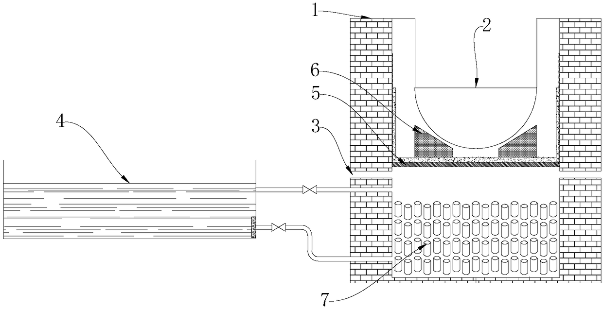
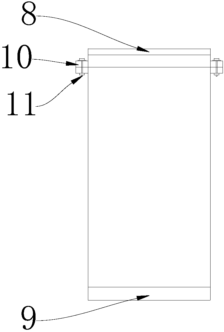
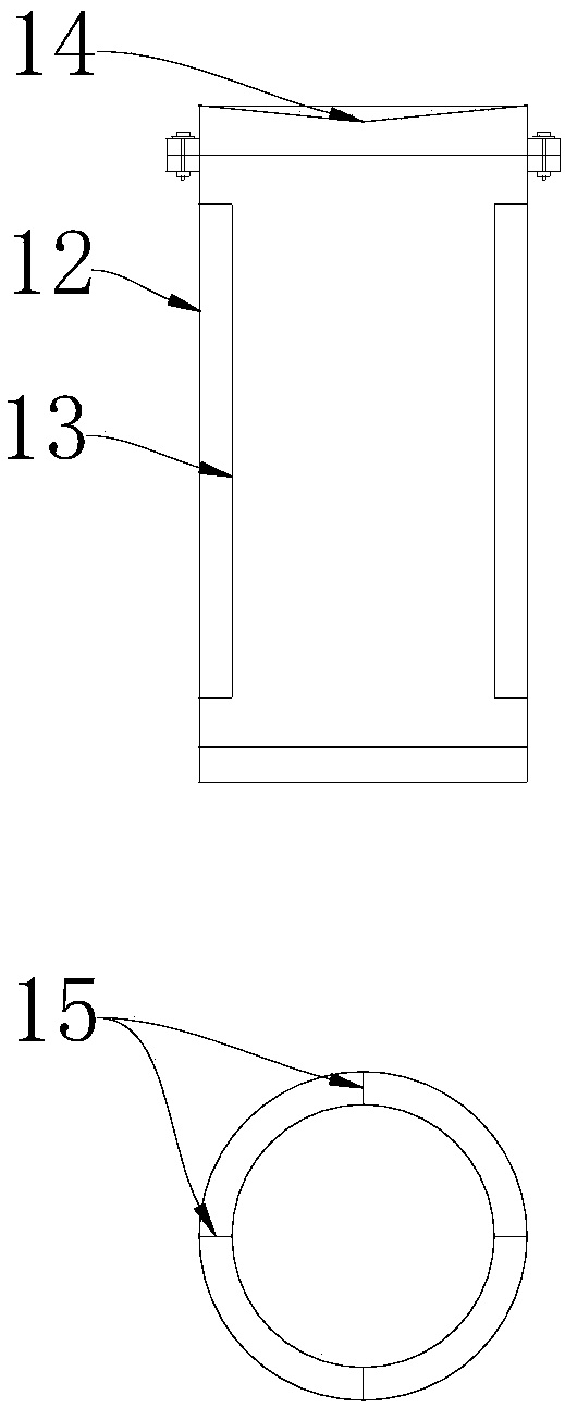
[0058] The composition and structure of the reactor core molten material capture device of the exemplary reactor pit direct retention of the present invention is as follows: Figure 1-4 As shown, it includes a reactor pit 1, a reactor pressure vessel 2, a steam discharge port 3, a cooling water tank 4, an inspection platform 5, a shock absorbing device 6, and a metal sealed tank 7.

[0059] The maintenance platform 5 is placed in the pit pile 1 and divides the pit pile 1 into upper and lower halves. The maintenance platform 5 is spliced ​​by glass plates with high mechanical strength (the glass plates have a structure of 2-4 layers, which are bonded with glass glue, and the thickness of each tempered glass plate is 10-15mm, and the load-bearing per unit area is not less than 1700kg). , and a layer of sacrificial concrete with a t...


PUM

PropertyMeasurementUnit
Thicknessaaaaaaaaaa

Abstract

The invention belongs to the technical field of nuclear safety control and relates to a reactor pit direct retention type reactor core melt capturing device of. The capturing device comprises a reactor pit, an overhauling platform, a reactor pressure container, metal sealing pots, a cooling water tank and a steam exhausting opening, wherein the overhauling platform is placed in the reactor pit andis used for dividing the reactor pit into upper and lower parts; the reactor pressure container is arranged at the upper half part in the reactor pit; the plurality of metal sealing pots are stackedon the lower half part in the reactor pit; after the lower half part in the reactor pit is filled with water, the metal sealing pots can be of a floating state in the reactor pit; the cooling water tank is located outside the reactor pit and forms a circulating loop with the lower half part in the reactor pit through a connection pipeline; the steam exhausting opening is formed in the upper part of a side wall of the lower half part in the reactor pit. The capturing device provided by the invention has a simple principle, is convenient to construct and amount, is easy to maintain and has highcooling efficiency and small negative risks and can cope with serious accident working conditions of the reactor.

Description

technical field [0001] The invention belongs to the technical field of nuclear safety control, and relates to a reactor core melting material collecting device directly detained in a reactor pit. Background technique [0002] A serious accident in a nuclear power plant begins with the large-scale melting of reactor fuel assemblies. At this time, the fuel cladding, the first barrier of the defense-in-depth system, has failed. If the fuel assemblies cannot be cooled in time, the related reactor internals will also be melted, and Core melt is formed and falls into the lower head of the reactor pressure vessel (RPV). In the case of insufficient external cooling of the RPV lower head, the RPV lower head will be melted, that is, the pressure boundary of the second barrier and the primary circuit is broken, and the core melt enters the containment vessel at this time. After the pressure vessel melts through, the core melt is sprayed directly onto the containment raft foundation to...

Claims


Application Information

Patent Timeline
IPC IPC(8): G21C9/016
CPCG21C9/016Y02E30/30
Inventor 元一单郭强李炜张丽朱晨马卫民韩旭
Owner CHINA NUCLEAR POWER ENG CO LTD
Why Eureka
Try Eureka