
Automatic test mechanical arm device based on vision calibration, control system and control method thereof

A control system and device control technology, applied in the direction of manipulators, program-controlled manipulators, claw arms, etc., can solve the problems of inaccurate positioning, no feedback device in the system, and inability to feedback errors, etc., to improve accuracy and real-time performance, and control quickly Accurate, anti-interference effect

Active Publication Date: 2018-09-18
江苏太航信息科技有限公司
View PDF4 Cites 9 Cited by
  • Summary
  • Abstract
  • Description
  • Claims
  • Application Information

AI Technical Summary

Problems solved by technology

[0004] (1) It is in an open-loop control state during the working process, and there is no feedback information during the movement of the robotic arm, so it is impossible to determine the actual situation of the robotic arm movement
[0005] (2) Cannot eliminate external interference independently
There will be more or less errors in artificial placement, and the above-mentioned system has no feedback device and cannot feed back errors
If the error is small, the positioning cannot be done accurately; if the error is too large, the system will not work properly.
[0006] (3) Can not meet the requirements of fast visual servo control
[0007] (4) The positioning accuracy is not high
The interference generated by the outside world and itself will reduce the accuracy of the identification and positioning of the subsequent test tubes, and effective measures cannot be taken to correct them. The accumulation of these interferences will greatly reduce the accuracy of the positioning of the test tubes in the entire system

Method used


Image

  • Automatic test mechanical arm device based on vision calibration, control system and control method thereof
  • Automatic test mechanical arm device based on vision calibration, control system and control method thereof
  • Automatic test mechanical arm device based on vision calibration, control system and control method thereof

Examples


Embodiment Construction

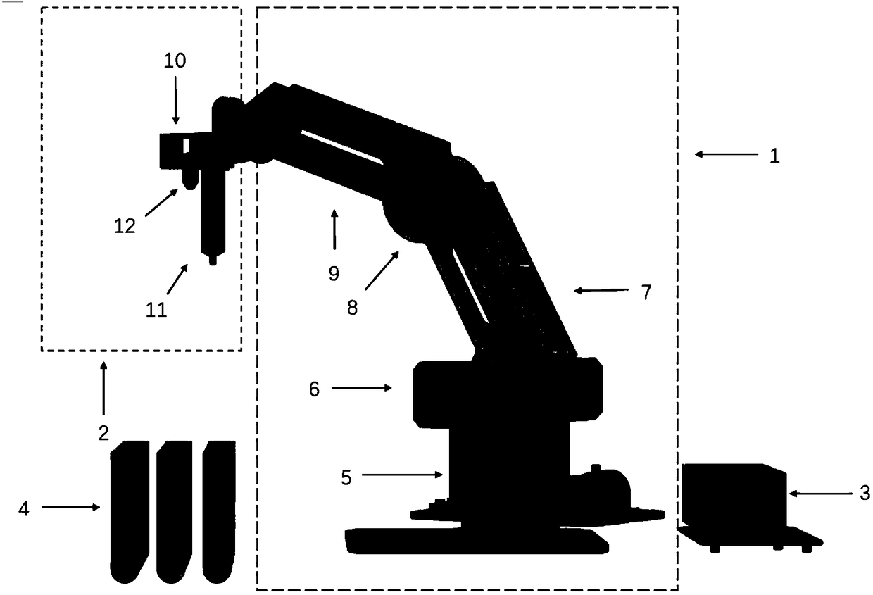
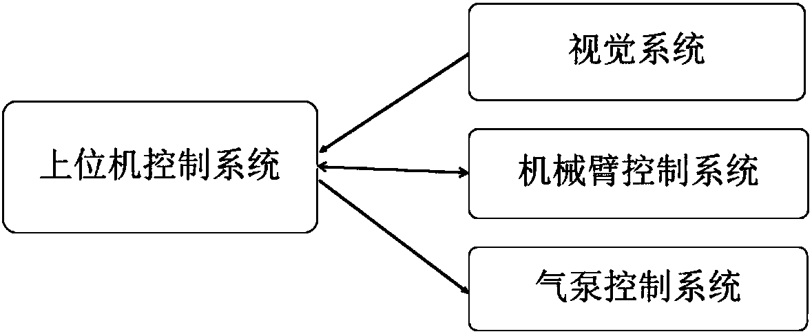
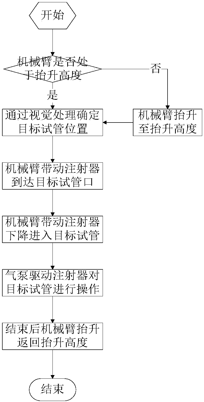
[0054]A new type of automatic testing robot arm device, control system and control method based on vision calibration of the present invention can automatically identify and locate the test tube and the position of the test tube rack through the visual system, and then realize automatic testing, which helps to reduce errors and improve testing efficiency. , Enhance the level of automation. Using monocular vision calibration, firstly, the three-dimensional model of the automatic testing robot arm and the test tube rack in space is established. Then, visually recognize the position of the test tube rack and locate each test tube arranged on the test tube rack. Furthermore, the movement of the mechanical arm in the operating space is controlled so that the mechanical arm drives the syringe mounted on the end effector of the mechanical arm to move to the test tube opening of the target test tube. Finally, the syringe is driven by the air pump to absorb or discharge the sample in ...


PUM


Abstract

The invention discloses an automatic test mechanical arm device based on vision calibration. The automatic test mechanical arm device based on vision calibration comprises a control system, a mechanical arm main body, an end executer, a gas pump and a test tube rack, wherein the mechanical arm main body comprises a first servo motor fixed to a support platform, a second servo motor adjacent to thefirst servo motor, a large arm connected with the second servo motor, a third servo motor connected with the large arm, and a small arm connected with the third servo motor; the mechanical arm main body is connected with the end executer through an L-shaped workpiece; the end executer comprises an injector and a camera; and the axis of the camera is vertical to the upper plane of the test tube rack. The gas pump is located behind the mechanical arm main body, and the injector is connected with the gas pump through a hose; and the gas pump is used for driving the injector to suck or drain a liquid. The automatic test mechanical arm device based on vision calibration is capable of realizing automatic test, and is high in interference resistance, repeatability and efficiency.

Description

technical field [0001] The invention belongs to the technical field of automatic inspection manipulators, and relates to a visual calibration-based automatic inspection manipulator device, a control system and a control method thereof. Background technique [0002] At present, most of the sampling methods used in the laboratory analysis instruments used in hospitals, scientific research and other units are manual operation modes, such as test tube insertion type and whole row push type, which consume manpower and cause problems due to different operators. Variations in post-processing. With the advancement of science and technology, the emergence of automatic inspection manipulators becomes possible. If the mechanical arm is positioned to the target test tube, the position of the target test tube must first be determined. As the "eyes" of the entire system, the vision system is used for the identification and positioning of target test tubes. Whether the target test tubes ...

Claims


Application Information

Patent Timeline
IPC IPC(8): B25J18/00B25J9/16B25J19/04G06T7/73G06T7/136G06T7/13G06T3/60
CPCB25J9/16B25J9/161B25J18/00B25J19/04G06T3/60G06T7/13G06T7/136G06T7/73
Inventor 于洋陈伟
Owner 江苏太航信息科技有限公司
Learn More