
Bidirectional powder paving device, powder feeding and paving device and additive manufacturing device

A technology of a powder spreading device and a powder feeding device, which is applied in the field of two-way powder spreading devices and additive manufacturing equipment, which can solve the problems of low powder spreading efficiency, large space occupation, and high equipment investment cost, and achieve improved powder spreading efficiency and simple structure , The effect of low equipment investment cost

Pending Publication Date: 2018-09-18
HUNAN FARSOON HIGH TECH CO LTD
View PDF10 Cites 8 Cited by
  • Summary
  • Abstract
  • Description
  • Claims
  • Application Information

AI Technical Summary

Problems solved by technology

[0003] In this traditional technology, every time sintering is carried out, the powder spreading device needs to reversely move back to the fixed powder feeding and powder laying position after finishing powder spreading along the powder spreading route, so as to start a new powder spreading work. This process increases The cycle time of each sintering is shortened, and the powder spreading efficiency is low
[0004] Changing one-way powder spreading to two-way powder spreading is an effective way to improve the efficiency of powder spreading, but the structure of the disclosed two-way powder spreading device is complicated. The roller can be rotated, or a powder supply trough with a complex switch mechanism is set, and some need to improve the adaptability of the powder feeding device, and the initial equipment investment cost is high

Method used


Image

  • Bidirectional powder paving device, powder feeding and paving device and additive manufacturing device
  • Bidirectional powder paving device, powder feeding and paving device and additive manufacturing device
  • Bidirectional powder paving device, powder feeding and paving device and additive manufacturing device

Examples


Embodiment Construction

[0034] In order to facilitate the understanding of the present invention, the present invention will be described more fully below with reference to the associated drawings. Preferred embodiments of the invention are shown in the accompanying drawings. However, the present invention can be embodied in many different forms and is not limited to the embodiments described herein. On the contrary, these embodiments are provided to make the understanding of the disclosure of the present invention more thorough and comprehensive.

[0035] It should be noted that when an element is referred to as being “fixed” to another element, it can be directly on the other element or there can also be an intervening element. When an element is referred to as being "connected to" another element, it can be directly connected to the other element or intervening elements may also be present.

[0036] Unless otherwise defined, all technical and scientific terms used herein have the same meaning as...


PUM


Abstract

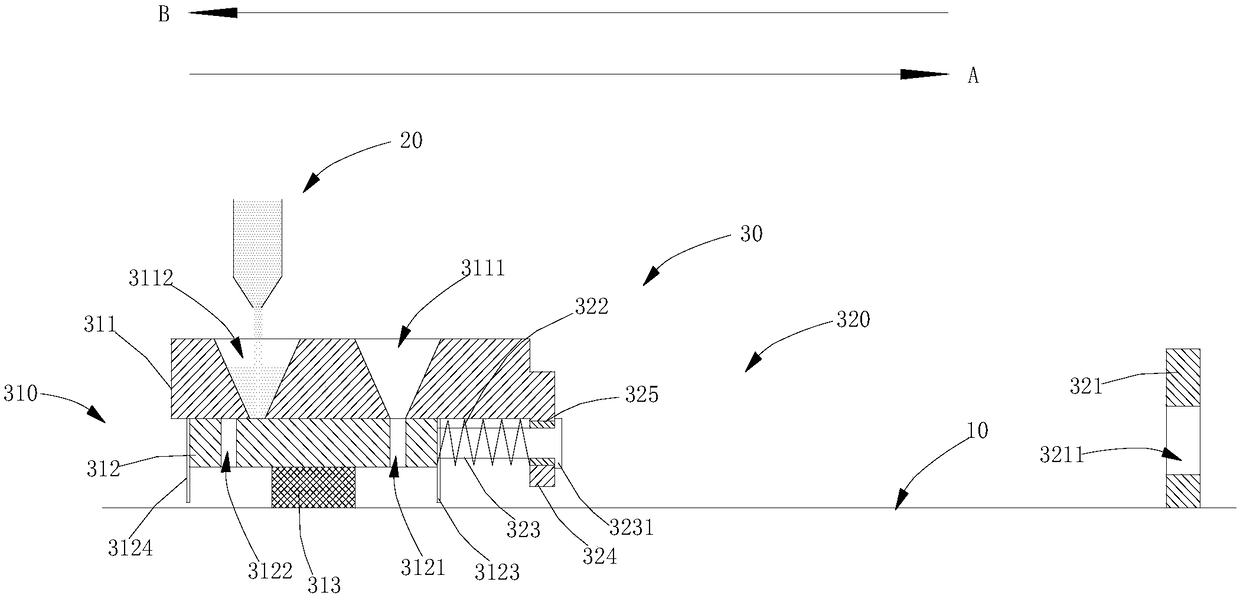
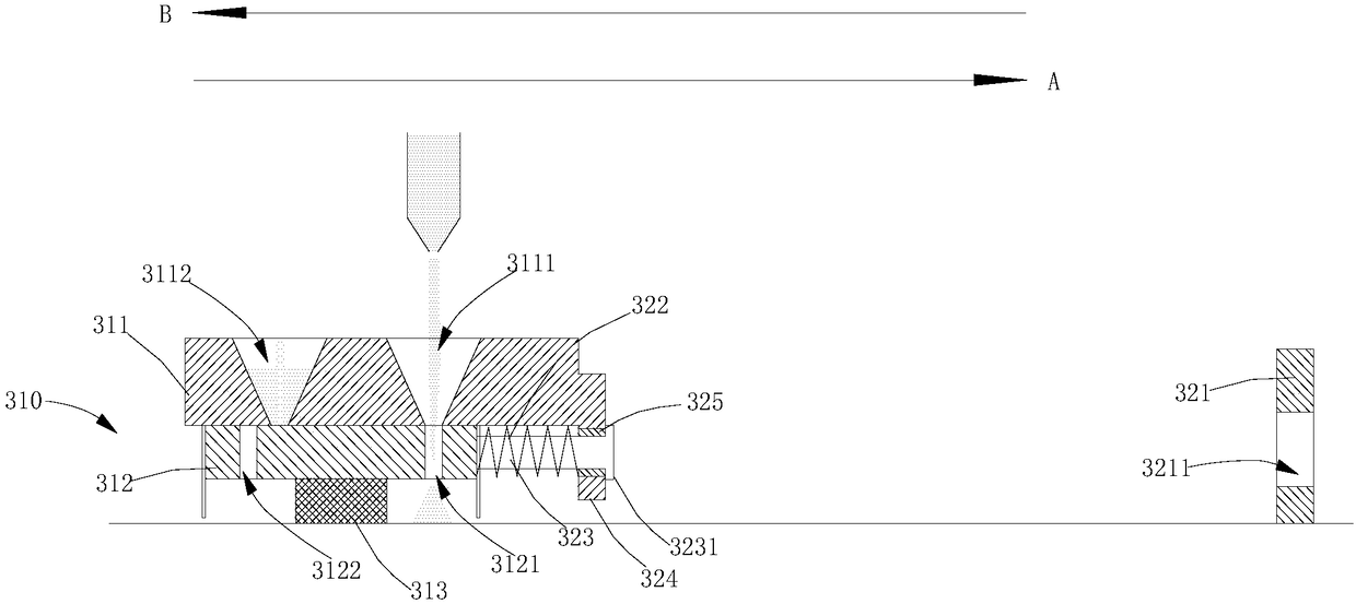
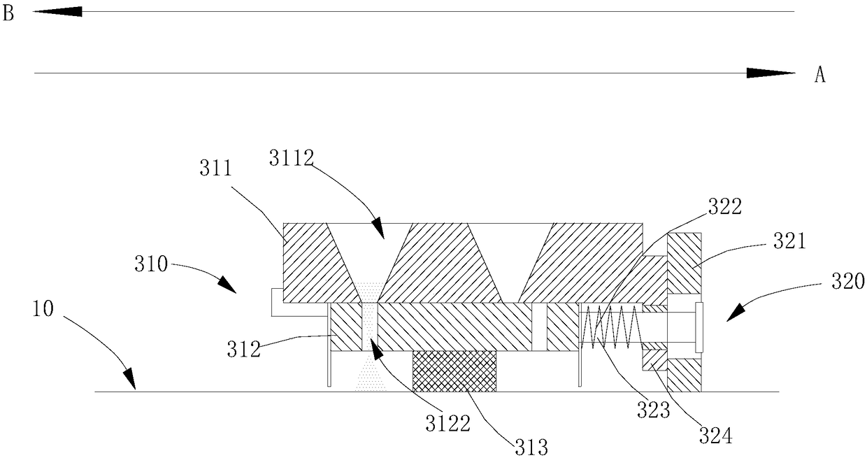
The invention relates to a bidirectional powder paving device. The bidirectional powder paving device comprises a powder paving mechanism, a driving mechanism and a adjusting mechanism; the powder paving mechanism comprises a powder feeding part, a scraper base and a scraper; the powder feeding part is arranged on the scraper base, and the scraper is fixed at the bottom of the scraper base; a forward powder feeding groove and a reverse powder feeding groove are formed in the powder feeding part, and the scraper base is provided with a forward powder falling hole and a reverse powder falling hole; the driving mechanism can drive the powder paving mechanism to reciprocate between a forward powder falling position and a reverse powder falling position along the powder paving path; and relative movement can be generated between the scraper base and the powder feeding part under the action of the adjusting mechanism to achieve switching between a forward conducting state and a reverse conducting state. According to the bidirectional powder paving device, twice powder falling and powder paving actions are realized when a scraper assembly drives a powder feeding plate to move back and forth in the length direction of a workbench, the powder paving efficiency is high, the structure is simple, and the device investment cost is low.

Description

technical field [0001] The invention relates to the technical field of additive manufacturing, in particular to a two-way powder spreading device and additive manufacturing equipment. Background technique [0002] The basic process of the traditional selective laser sintering process is: the powder feeding device sends a certain amount of additive manufacturing powder to the working table of the molding cylinder, and the conventional powder spreading device spreads the powder on the working table On the upper surface of the molded part, the heating device heats the powder to a set temperature, and the laser galvanometer system controls the laser to scan the powder located in the contour according to the cross-sectional contour of the layer, so that these powders are melted and combined with the formed part below. Bonding; when the section of one layer is sintered, the workbench is lowered by one layer thickness, the powder feeding device and the powder spreading device repea...

Claims


Application Information

Patent Timeline
Patent Type & Authority Applications(China)
IPC IPC(8): B29C64/153B29C64/214B29C64/20B29C64/205B29C64/321B33Y30/00B33Y40/00
CPCB29C64/153B29C64/20B29C64/205B29C64/214B29C64/321B33Y30/00B33Y40/00Y02P10/25
Inventor 赵太传周智阳王菲刘鑫炎
Owner HUNAN FARSOON HIGH TECH CO LTD
Learn More