Lead-acid storage battery and exhaust valve assembly

An exhaust valve and battery technology, applied in lead-acid batteries, lead-acid battery construction, electrical components, etc., can solve the problems of corrosive acid mist not easily discharged, unstable opening and closing valve pressure, and low processing accuracy.

Pending Publication Date: 2018-09-18
SHANDONG SACRED SUN POWER SOURCES
View PDF0 Cites 1 Cited by
  • Summary
  • Abstract
  • Description
  • Claims
  • Application Information

AI Technical Summary

Problems solved by technology

[0003] At present, there are mainly two types of exhaust valves used in domestic lead-acid batteries: one is to directly install a rubber cap on the liquid injection hole of the battery cover, and use the cover sheet to encapsulate it, which is usually called a rubber cap valve. The structure of the valve is simple and the price is low, but the processing accuracy is low, the pressure of the opening and closing valve is unstable, and the corrosive acid mist is easy to discharge; the second is to design the exhaust valve as a separate part, and it is connected to the battery by thread or buckle. The liquid holes are assembled and connected together, usually called a split valve. The exhaust valve with this structure has high machining accuracy, stable opening and closing valve pressure, and corrosive acid mist is not easy to discharge. However, the above two exhaust valve structures are practical in the battery Serious dehydration phenomenon exists in the working process, which will lead to rapid loss of moisture inside the battery, which seriously restricts the overall performance and service life of the battery

Method used


Image

  • Lead-acid storage battery and exhaust valve assembly
  • Lead-acid storage battery and exhaust valve assembly
  • Lead-acid storage battery and exhaust valve assembly

Examples


Embodiment Construction

[0024] The core of the present invention is to provide an exhaust valve assembly, the exhaust valve assembly has high processing precision, has a relatively stable opening and closing valve pressure, and can effectively reduce the water loss and Acid mist discharge; at the same time, a lead-acid battery using the above-mentioned exhaust valve assembly is provided.

[0025] In order to enable those skilled in the art to better understand the solution of the present invention, the present invention will be further described in detail below in conjunction with the accompanying drawings and specific embodiments.

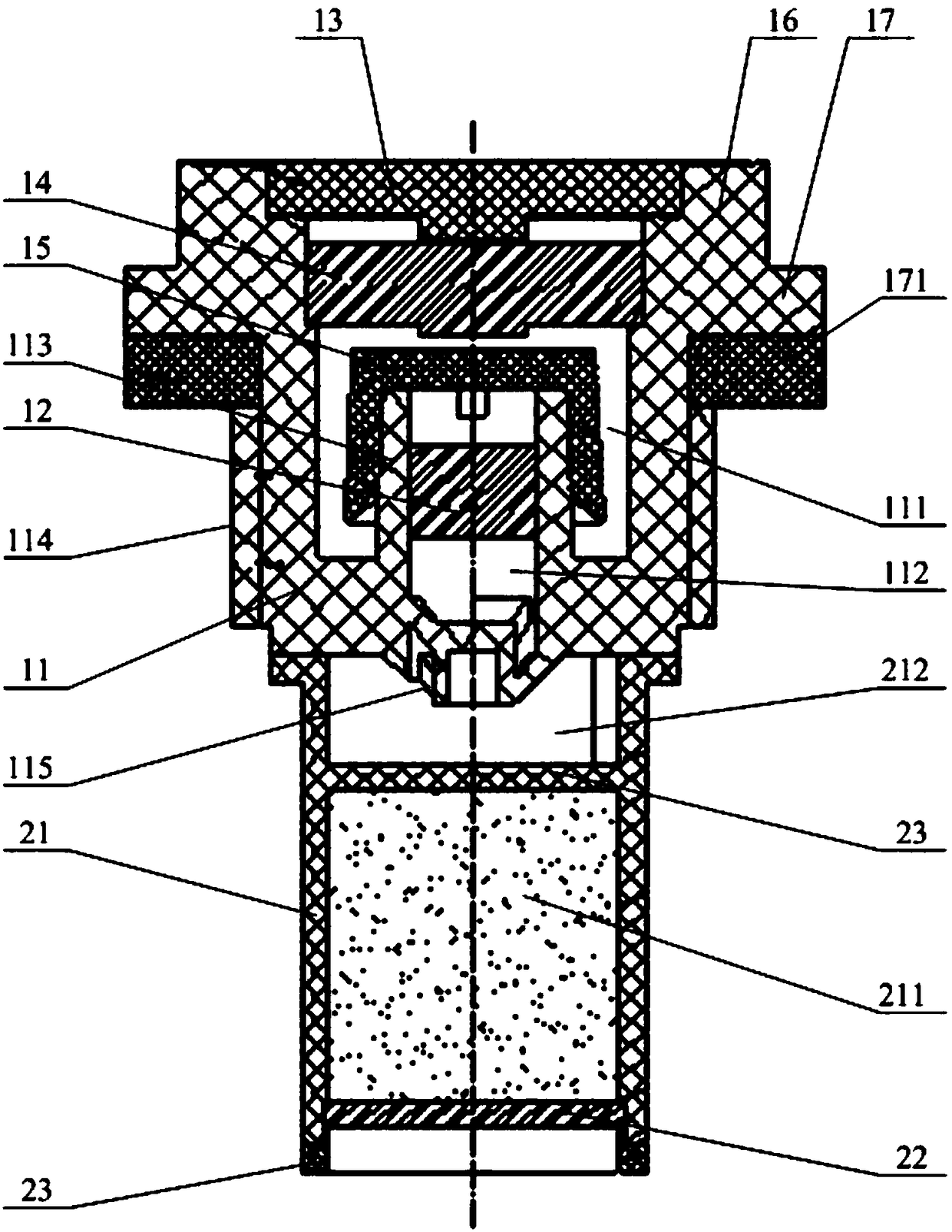
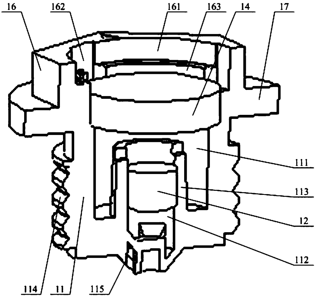
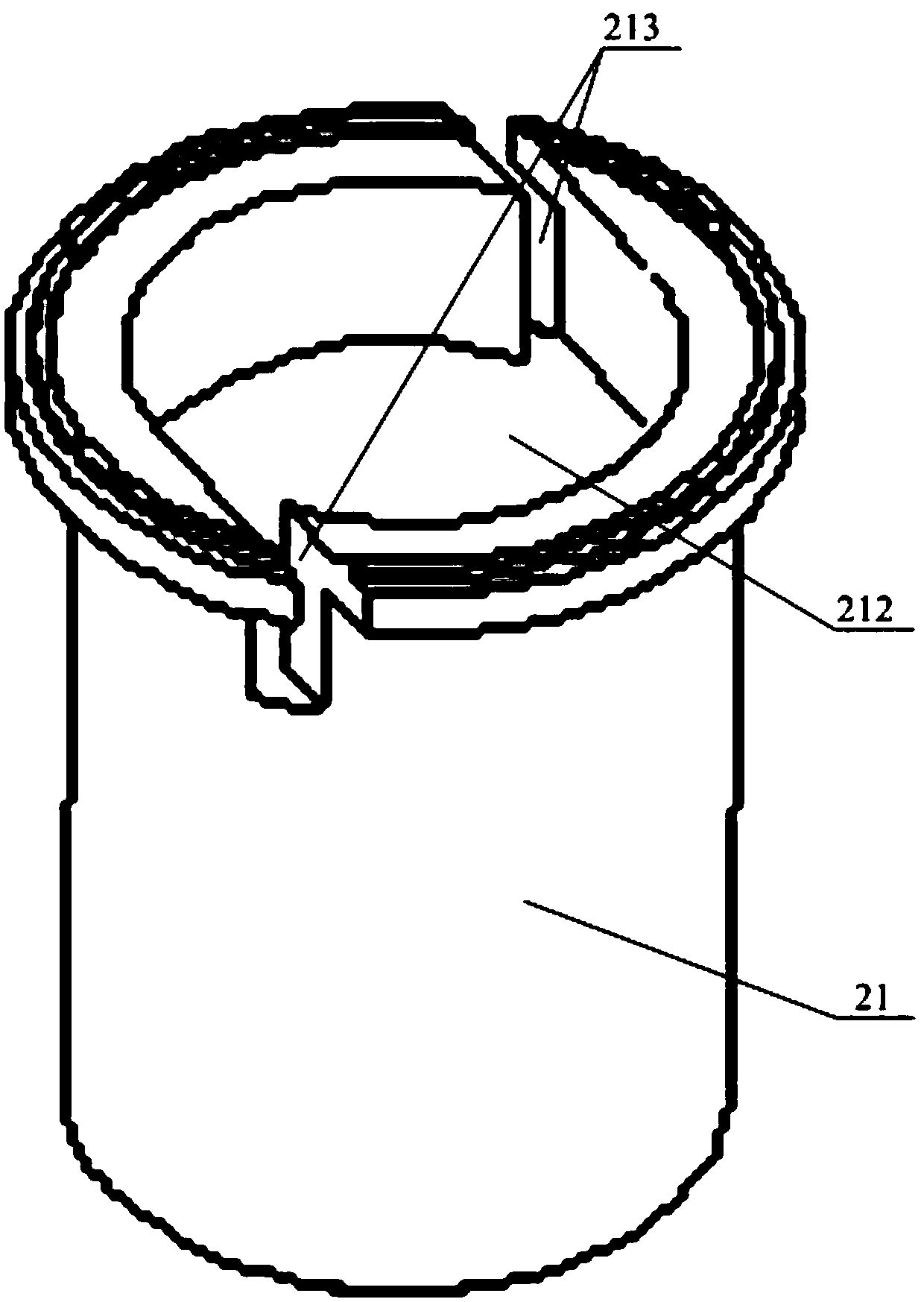
[0026] Please refer to Figure 1 to Figure 4 , figure 1 A structural sectional view of the lead-acid storage battery provided for a specific embodiment of the present invention; figure 2 for figure 1 A cutaway view of the three-dimensional structure of the middle valve body; image 3 for figure 1 Schematic diagram of the three-dimensional structure of the middle pl...


PUM


Abstract

The invention discloses an exhaust valve assembly which comprises a valve body arranged at the top of a storage battery shell and a plug body positioned in an inner cavity of a storage battery and connected to the bottom of the valve body. A reaction cavity which can accommodate a catalyst and is communicated with the inner cavity of the storage battery is formed at the middle part of the plug body; a lower acid filtering sheet is arranged at the bottom of the reaction cavity; a valve cavity is formed inside the valve body; an air passage communicated with the inner cavity of the storage battery is formed at the bottom of the valve cavity; a middle acid filtering sheet is arranged at the middle part of the air passage; a cover plate is arranged at the top of the valve cavity; an upper acidfiltering sheet is arranged between the cover plate and the middle acid filtering sheet; and the valve body is provided with an exhaust port for communicating the valve cavity with the external environment. The exhaust valve assembly is high in machining accuracy and can effectively reduce water loss and an acid mist discharge rate of a lead-acid storage battery in the working process. The invention further discloses a lead-acid storage battery applying the exhaust valve assembly.

Description

technical field [0001] The invention relates to the technical field of lead-acid battery supporting components and technology, in particular to an exhaust valve assembly. The invention also relates to a lead-acid storage battery using the exhaust valve assembly. Background technique [0002] The exhaust valve is an important component of lead-acid battery products. Its function is: when the gas pressure inside the battery rises to a certain value, the exhaust valve will automatically open to allow the gas to be discharged; when the gas pressure inside the battery drops to a certain value When the exhaust valve is closed automatically, no air is allowed to enter. The lead-acid battery is sealed to the battery through the exhaust valve part, which can reduce the maintenance of adding water during use, and can also reduce the loss of water and the discharge of corrosive acid mist during use. Therefore, the quality and structural characteristics of the exhaust valve have a dir...

Claims


Application Information

Patent Timeline
IPC IPC(8): H01M2/12H01M10/12H01M50/30
CPCH01M10/12H01M50/30Y02E60/10Y02P70/50
Inventor 孔德龙刘常升范娜王金生祝青凯高海洋付洪运曹纪豹
Owner SHANDONG SACRED SUN POWER SOURCES
Why Eureka
Try Eureka