
Device for carrying out combined machining on plane by electrolytic magnetic force

A composite processing and flat technology, applied in metal processing equipment, manufacturing tools, grinding/polishing equipment, etc., can solve the problem of unsatisfactory polishing effect on the surface of cemented carbide plates, saving manpower, improving efficiency and saving electricity Effect

Pending Publication Date: 2018-09-21
UNIV OF SCI & TECH LIAONING
View PDF0 Cites 0 Cited by
  • Summary
  • Abstract
  • Description
  • Claims
  • Application Information

AI Technical Summary

Problems solved by technology

[0004] Both magnetic grinding and electrochemical machining are special processing methods today, but neither the magnetic grinding technology nor the electrochemical processing technology is ideal for surface polishing of cemented carbide plates, and each has its own shortcomings, such as: magnetic grinding The usual way to process polished flat plates is to use a milling machine to install magnetic poles on the milling machine spindle, and to absorb magnetic abrasives through the magnetic force of the magnetic poles to form a "magnetic brush"
However, since there are too many factors involved in the processing process, such as the flow field of the electrolyte, the electric field between the electrodes, and the temperature field, etc., all have an impact on the processing, to achieve good processing efficiency and surface quality requires high process control and equipment requirements.

Method used


Image

  • Device for carrying out combined machining on plane by electrolytic magnetic force
  • Device for carrying out combined machining on plane by electrolytic magnetic force
  • Device for carrying out combined machining on plane by electrolytic magnetic force

Examples


Embodiment Construction

[0021] The specific implementation manner of the present invention will be further described below in conjunction with the accompanying drawings.

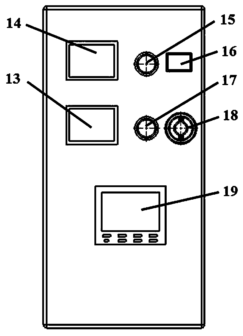
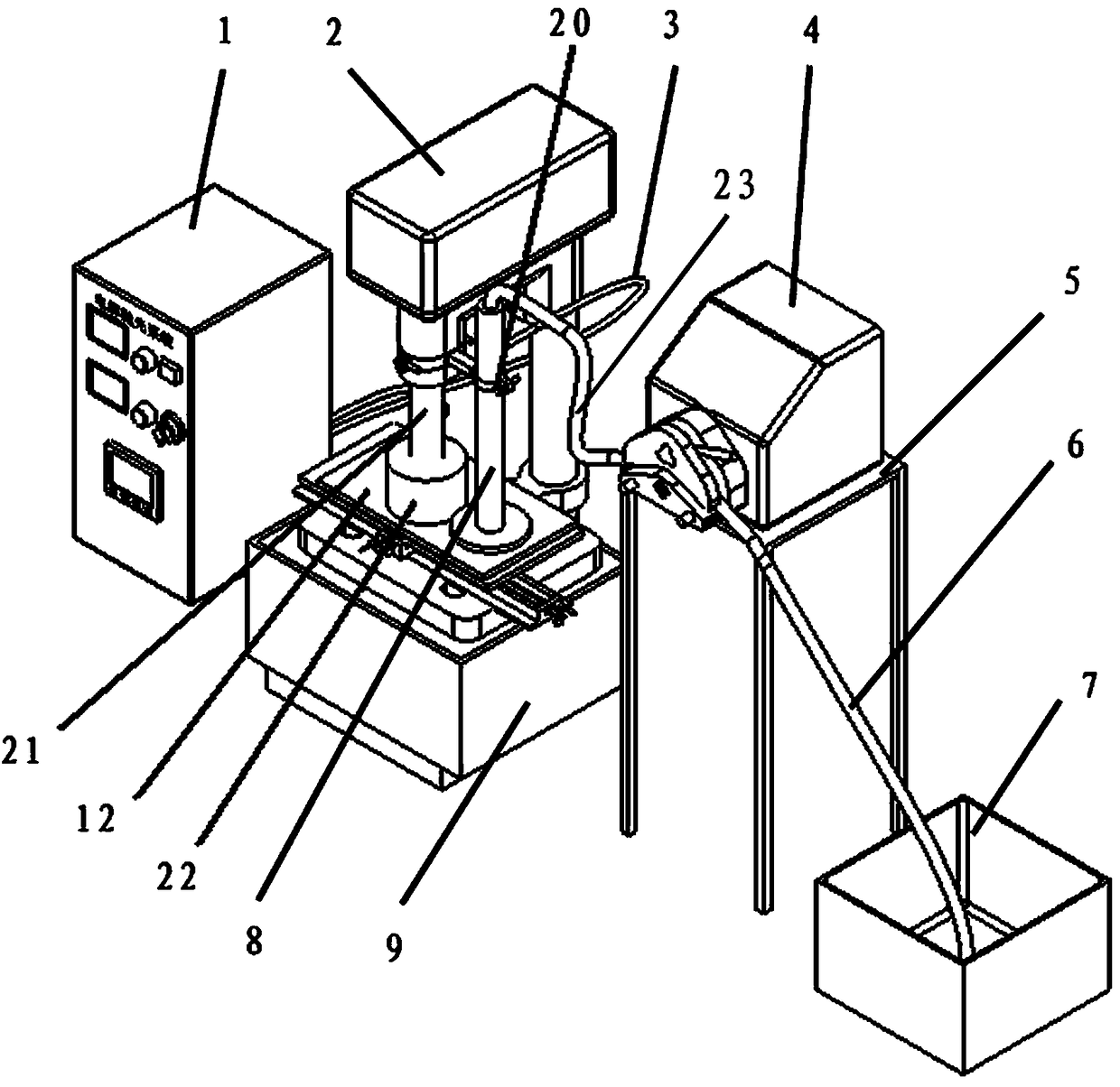
[0022] Such as figure 1 , 2 Shown in and 3, the device of electrolytic magnetic composite machining plane of the present invention comprises milling machine 2, is arranged on the adjustable horizontal workbench 11 on this milling machine 2, is characterized in that described milling machine 2 is provided with described milling machine The fixed holder 20 fixedly connected to the main shaft 21 is provided with an electrolytic polishing device connected to the fixed holder 20 on the milling machine 2, and a magnetic grinding device is provided at the end of the main shaft 21 of the milling machine.

[0023] The electrolytic polishing equipment includes a hollow copper rod 8 clamped by the fixed holder 20 and vertically arranged on the surface of the adjustable horizontal workbench 11, and a cathode wire connected to the hollow coppe...


PUM


Abstract

The invention belongs to the technical field of ultraprecision machining, and particularly relates to a device for carrying out combined machining on a plane by electrolytic magnetic force. The devicecomprises a milling machine and an adjustable horizontal workbench, and is characterized in that the milling machine is provided with a fixed clamper, electrolytic polishing equipment and magnetic force grinding equipment; the electrolytic polishing equipment comprises a hollow copper rod, a cathode line connected with the hollow copper rod, an anode line connected with a workpiece to be processed, an electrolytic polishing control system, a peristaltic pump connected with the hollow copper rod through a first silica gel pipe, and an electrolyte tank connected with the peristaltic pump through a second silica gel pipe; the magnetic force grinding equipment comprises an axial magnetic pole connected with a main shaft of the milling machine to carry out magnetic material grinding. The device makes up the deficiencies of single-type processing, the material of a workpiece surface is softened through the anode dissolution reaction of electrochemistry, so that the workpiece surface is ground by magnetic force grinding, the anode dissolution reaction of electrochemical machining can be continuously carried out, magnetic force-ground materials can be softened, and the surface accuracy ofthe machined workpiece is high.

Description

technical field [0001] The invention belongs to the technical field of ultra-precision machining, and in particular relates to a device for electrolytic magnetic composite machining of planes. Background technique [0002] Cemented carbide is used as important parts in many fields such as aerospace and ships. The surface quality of these parts has a great impact on the entire equipment, so it is indispensable for their processing. However, for these cemented carbides Surface processing and its high-efficiency processing are currently facing difficulties. [0003] Especially for the polishing of large-area metal plates, due to the limitation of the shape of the plate and the processing method, the traditional polishing method usually uses a surface grinder for grinding and polishing. This process includes rough grinding, semi-fine grinding, fine grinding to The surface appears mirrored. If it is a cemented carbide plate, it is more difficult to apply this method in the poli...

Claims


Application Information

Patent Timeline
IPC IPC(8): B24B1/00B24B57/02
CPCB24B1/005B24B57/02
Inventor 韩冰许召宽刘新龙赵杨刘顺刘冬冬钱之坤
Owner UNIV OF SCI & TECH LIAONING
Learn More