Large-pressure-angle worm driving mechanism

A technology of worm drive and high pressure, which is applied in transmission devices, friction transmission devices, mechanical equipment, etc., can solve the problems of worm gear or helical gear teeth that are easy to fail, and achieve high reliability, prolong working life, huge social benefits and The effect of economic benefits

Active Publication Date: 2018-09-21
JIANGSU UNIV OF TECH
View PDF16 Cites 0 Cited by
  • Summary
  • Abstract
  • Description
  • Claims
  • Application Information

AI Technical Summary

Problems solved by technology

[0005] In order to solve the problem that the teeth of the worm gear or helical gear meshed with the worm in the worm drive system in the prior art are prone to failure, the present invention provides a large pressure angle worm drive mechanism

Method used


Image

  • Large-pressure-angle worm driving mechanism

Examples


Embodiment 1

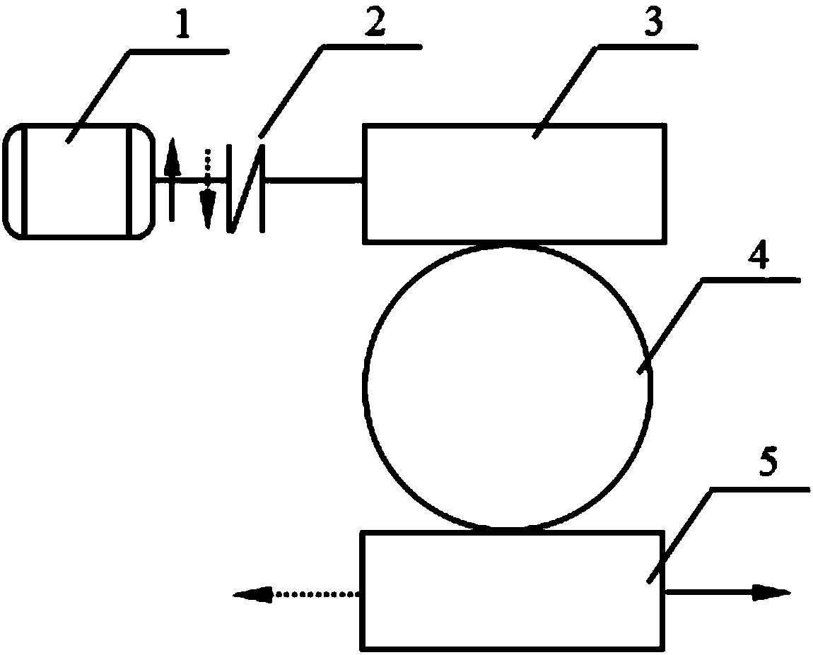
[0021] 1) For the convenience of analysis, it is assumed that the helical direction of the teeth of the worm 3 is left-handed. Take transmission wheel 4 as worm gear, because worm gear meshes with worm screw 3, then the gear tooth spiral direction of worm gear is also left-handed, and worm gear drives helical rack 5 to move, then the gear tooth helical direction of helical rack 5 is right-handed;

[0022] 2), such as figure 1 As shown, when the motor 1 rotates in the direction of the upward solid arrow, the worm 3 is driven to rotate through the coupling 2, and the rotation direction of the worm 3 is the same as that of the motor 1;

[0023] 3), take the number of heads, diameter coefficient, axial surface modulus, and axial surface pressure angle of the worm 3 as z 3 ,q 3 、m x3 、α x3 , where z 3 ,q 3 The value of can refer to the gear design manual; m x3 、α x3 It can be customized or obtained from the gear manual according to the needs, but the specific value is relat...

Embodiment 2

[0031] 1) For the convenience of analysis, it is assumed that the helical direction of the teeth of the worm 3 is left-handed, and the transmission wheel 4 is taken as a helical gear. Since the helical gear meshes with the worm 3, the helical direction of the helical teeth of the helical gear is also left-handed, and the helical gear drives When the helical rack 5 moves, the helical direction of the teeth of the helical rack 5 is right-handed;

[0032] 2), such as figure 1 As shown, when the motor 1 rotates in the direction of the upward solid arrow, the worm 3 is driven to rotate through the coupling 2, and the rotation direction of the worm 3 is the same as that of the motor 1;

[0033] 3), take the number of heads, diameter coefficient, axial surface modulus, and axial surface pressure angle of the worm 3 as z 3 ,q 3 、m x3 、α x3 , where z 3 ,q 3 The value of can refer to the gear design manual; m x3 、α x3 The value can be determined according to the needs or taken fro...


PUM


Abstract

The invention belongs to the technical field of worm driving designs, and particularly relates to a large-pressure-angle worm driving mechanism. The large-pressure-angle worm driving mechanism comprises a worm, a driving wheel meshed with the worm and a skew rack meshed with the driving wheel. The large-pressure-angle worm driving mechanism meets the following conditions: picking an axial plane modulus of the worm as mx3, and an axial plane pressure angle as ax3, picking an end face modulus of the driving wheel as mt4, an end face pressure angle as at4, picking an end face modulus of the skewrack as mt5, and an end face pressure angle as at5; the worm is meshed with the driving wheel, meeting mt4cosat4=mx3cosax3, and at4 is greater than ax3; and the driving wheel is meshed with the skew rack, meeting mt5cosat5=mt4cosat4, and at4 is greater than at5, and the driving wheel is the worm or the skew rack. The beneficial effect is that the large-pressure-angle worm driving mechanism has theadvantages of large bearing capacity, long service life, high reliability, difficult tooth breaking, easy machining and the like; because the worm driving is extensively applied to the industries ofhome appliances, automobiles, instruments, hoisting machinery and the like, the market prospect is broad, and the large-pressure-angle worm driving mechanism has the huge social benefit and economic benefit.

Description

technical field [0001] The invention belongs to the technical field of worm drive design, in particular to a large pressure angle worm drive mechanism. Background technique [0002] Worm drive is widely used because of its advantages such as large transmission ratio, stable transmission, small vibration and low noise. The performance and quality of worm drive will ultimately affect the quality of machine products. Therefore, in order to meet people's growing The needs of modern material and cultural life require the continuous optimization of the transmission performance of the worm. [0003] The failure mode of worm drive often manifests as tooth surface pitting, gluing, wear and tooth breakage, etc. Once the gear teeth are broken, it will affect the normal operation of the worm drive system, and even cause equipment accidents and casualties in severe cases. Due to material and structural reasons, the strength of the helical tooth part of the worm is always higher than th...

Claims


Application Information

Patent Timeline
IPC IPC(8): F16H19/04F16H55/22F16H55/17
CPCF16H19/043F16H55/17F16H55/22Y02E10/50
Inventor 李秀莲刘伟汪献伟徐旭松朱福先周金宇施晓芳王海峰俞成涛王江涛何庆刘志凯丁苏杭
Owner JIANGSU UNIV OF TECH
Why Eureka
Try Eureka