High-frequency in-situ imaging fatigue tester

A fatigue testing machine and testing machine technology, applied in the direction of applying repetitive force/pulse force to test the strength of materials, measuring devices, instruments, etc., to achieve the effects of high reliability, high-speed response, and high precision

Pending Publication Date: 2018-09-21
SOUTHWEST JIAOTONG UNIV
View PDF0 Cites 12 Cited by
  • Summary
  • Abstract
  • Description
  • Claims
  • Application Information

AI Technical Summary

Problems solved by technology

Existing in-situ imaging fatigue testing machines can only perform low-cycle fatigue testing

Method used


Image

  • High-frequency in-situ imaging fatigue tester
  • High-frequency in-situ imaging fatigue tester
  • High-frequency in-situ imaging fatigue tester

Examples


Embodiment Construction

[0029] The present invention will be described in further detail below through specific implementation examples and in conjunction with the accompanying drawings.

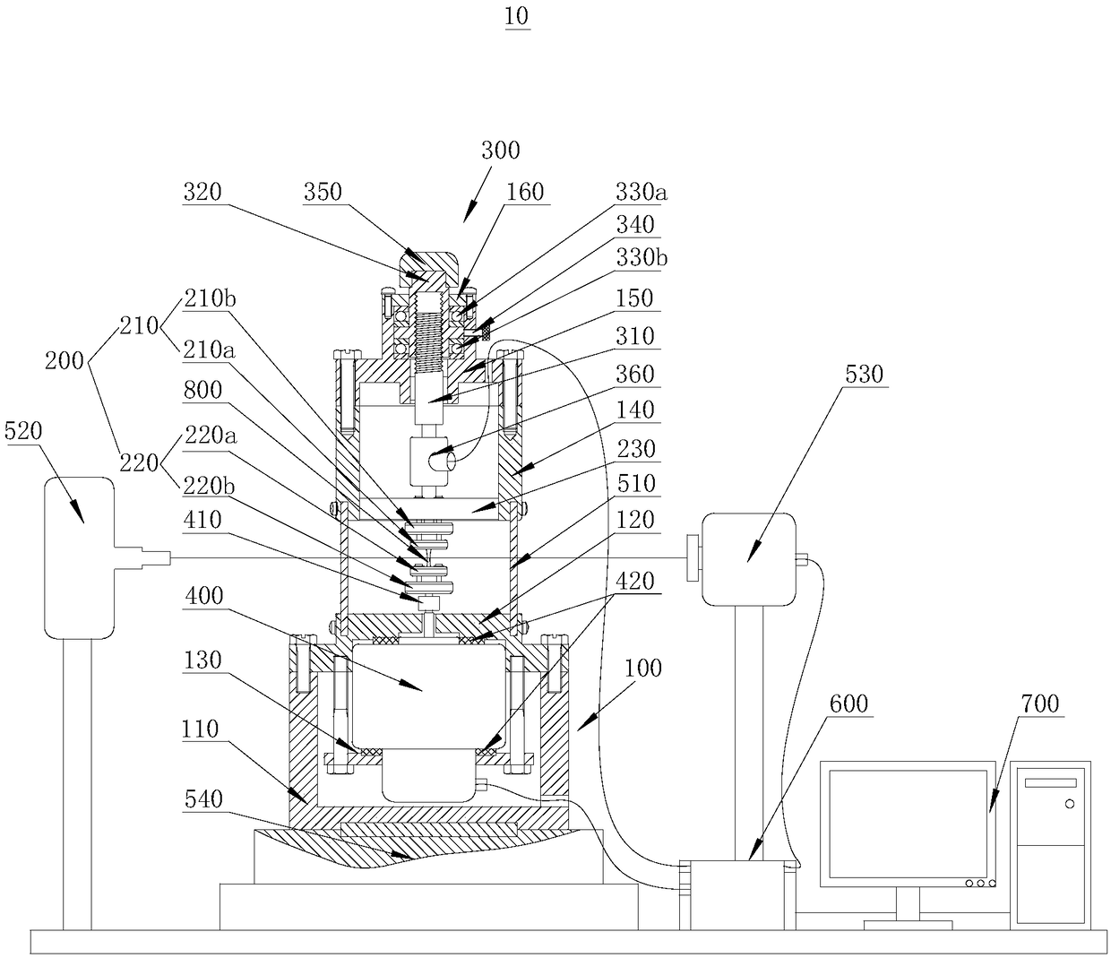
[0030] See attached figure 1 , a high-frequency in-situ imaging fatigue testing machine 10 provided by an embodiment of the present invention includes: a testing machine body 100 , a sample clamping mechanism 200 , a preset force loading mechanism 300 and a voice coil motor 400 .

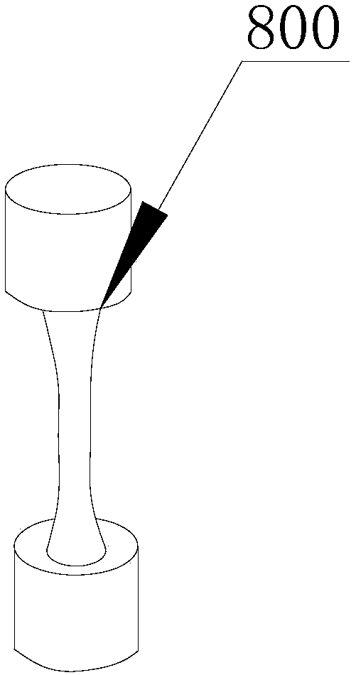
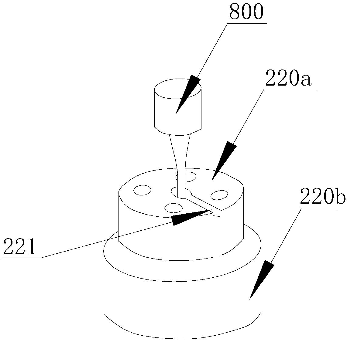
[0031] Wherein, the sample clamping mechanism 200 is used to clamp and fix the sample 800 , and the sample clamping mechanism 200 includes a first clamping assembly 210 and a second clamping assembly 220 which are oppositely arranged. The preset force loading mechanism 300 is disposed on the side of the first clamping assembly 210 of the sample clamping mechanism 200 , and is used to apply a preset tensile force to the sample 800 . The voice coil motor 400 is fixedly connected to the testing machine body 100 , and the actuating shaft of...


PUM


Abstract

The invention relates to the technical field of material testing and particularly relates to a high-frequency in-situ imaging fatigue tester. The tester comprises a tester body, a test sample clampingmechanism, a preset force loading mechanism and a voice coil motor, wherein the test sample clamping mechanism is used for clamping and fixing a test sample, and the test sample clamping mechanism comprises a first clamping assembly and a second clamping assembly which are arranged oppositely; the preset force loading mechanism is arranged at one side of the first clamping assembly of the test sample clamping mechanism and is used for applying preset tension and pressure to the test sample; and the voice coil motor is fixedly connected to the tester body, and a moving shaft of the voice coilmotor is connected to the second clamping assembly. The voice coil motor is utilized for realizing high-frequency actuation to perform high-frequency fatigue on the test sample, and high-energy X-raysare utilized for performing three-dimensional imaging on fatigue damage inside materials, thereby researching the high-cycle and even ultra-high-cycle fatigue failure mechanism of the materials.

Description

technical field [0001] The invention relates to the technical field of material testing, in particular to a high-frequency in-situ imaging fatigue testing machine. Background technique [0002] Fatigue of materials and structures has been a long-term focus of academic and engineering circles. Traditional methods such as optical microscopy and electron microscopy can only obtain fatigue cracks on the surface of materials, while three-dimensional fatigue cracks and their coupling behaviors caused by internal pores, slag inclusions, and tissues completely different from the surface. The combination of in-situ fatigue testing machine and advanced synchrotron radiation X-ray imaging technology enables scientists to penetrate deep into the material, non-destructively and in-situ to detect the process of fatigue damage and fracture and its evolution law in real time. However, the traditional fatigue testing machine uses a stepper motor as the driving device, and the stepper motor ...

Claims


Application Information

Patent Timeline
Patent Type & Authority Applications(China)
IPC IPC(8): G01N3/38G01N3/04
CPCG01N3/38G01N3/04G01N23/04G01N2203/0005G01N2203/005G01N2203/0073G01N2203/0244G01N2203/0647
Inventor 吴圣川吴正凯宋哲康国政胡雅楠刘宇杰
Owner SOUTHWEST JIAOTONG UNIV
Why Eureka
Try Eureka