Forced pressure-in-draw-out type turbogenerator ventilation cooling system with multi-wind path interleaving

A turbogenerator, ventilation and cooling technology, applied in the direction of cooling/ventilation device, magnetic circuit shape/style/structure, electric components, etc., can solve the problem of increasing fluid flow, reducing thermal stress of turbogenerator, high temperature, etc. problem, achieve the effect of increasing the total fluid flow, speeding up the flow rate and reducing thermal stress

Active Publication Date: 2018-09-21
HARBIN UNIV OF SCI & TECH
View PDF8 Cites 4 Cited by
  • Summary
  • Abstract
  • Description
  • Claims
  • Application Information

AI Technical Summary

Problems solved by technology

[0004] The purpose of the present invention is to provide a forced press-in-draw-out turbogenerator ventilation and cooling system interwoven with multiple air paths to solve the excessive temperature of each component caused by the unreasonable ventilation design of the entire space area of ​​a large-capacity turbogenerator. The high problem increases the total fluid flow in the turbogenerator, improves the utilization rate of the cooling gas in the turbogenerator, speeds up the flow speed of the cooling gas, and effectively reduces the The temperature of the components reduces the thermal stress in the axial direction of the turbo-generator and improves the safe and stable operation of the large-capacity turbo-generator

Method used


Image

  • Forced pressure-in-draw-out type turbogenerator ventilation cooling system with multi-wind path interleaving
  • Forced pressure-in-draw-out type turbogenerator ventilation cooling system with multi-wind path interleaving
  • Forced pressure-in-draw-out type turbogenerator ventilation cooling system with multi-wind path interleaving

Examples


specific Embodiment approach 1

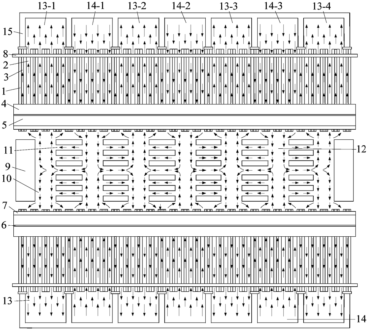
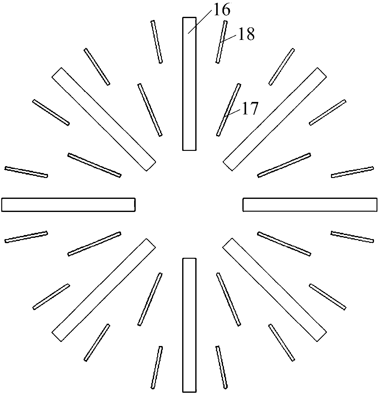
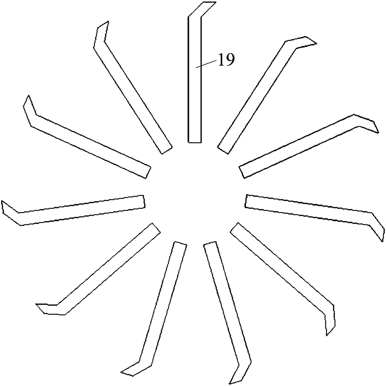
[0027] Embodiment 1: Combining figure 1 , figure 2 , image 3 , Figure 4 and Figure 5Illustrating this embodiment, a forced press-in-extraction type turbo-generator ventilation and cooling system with interlaced multi-air paths described in this embodiment includes a stator iron core 1, a stator radial ventilation ditch 2, and a "Y"-shaped stator. Internal ventilation channel 3, stator lower winding 4, stator upper winding 5, interlayer insulation 6, slot wedge 7, positioning ribs 8, rotor core 9, rotor hot air area 10, rotor axial ventilation hole 11, rotor cold air area 12, stator Hot air area 13, stator cold air area 14, stator frame 15, rotor throw-out fan blades 16, rotor first-stage pressurized fan blades 17, rotor second-stage pressurized fan blades 18, rotor suction fan blades 19 and stator groove 20. "Y"-shaped stator internal ventilation channel 3 includes stator I-type inner cooling ventilation channel 3-1 and stator V-shaped inner cooling ventilation channe...

specific Embodiment approach 2

[0030] Specific implementation mode 2: Combining Image 6 and Figure 7 Describing this embodiment, the difference between this embodiment and the first embodiment is that the inlet area of ​​the stator radial ventilation groove 2 in the stator hot air area 13 and the stator cold air area 14 is increased, and the entry into the stator radial ventilation groove 2 is increased. The flow rate of the cooling gas improves the ability of the cooling gas to take away the heat of the stator core 1 , and further reduces the temperature of the stator core 1 . Other components and connection relationships are the same as those in the first embodiment.

specific Embodiment approach 3

[0031] Specific implementation three: combination Figure 8 Describing this embodiment, the difference between this embodiment and the first embodiment is that the number of the rotor second stage pressurizing fan blades 18 is increased, which further increases the pressure of the cooling gas, accelerates the flow rate of the cooling gas, and effectively improves the The utilization rate of the cooling gas further reduces the temperature of the stator core 1 and the rotor core 9 . Other components and connection relationships are the same as those in the first embodiment.


PUM


Abstract

The invention discloses a forced pressure-in-draw-out type turbogenerator ventilation cooling system with multi-wind path interleaving, which relates to the field of electric machinery. In order to solve the problem of high temperature of a stator iron core, a stator winding and a rotor iron core in an existing turbogenerator, a 'Y'-shaped stator internal air channel is formed in the stator iron core, a stator radial ventilation groove is reserved between the stator iron cores, the stator region is alternately divided into a stator hot air area and a stator cold air area along the axial direction, and the stator iron core is arranged in the stator base; the rotor area is alternately divided into a rotor hot air area and a rotor cold air area along the axial direction, the rotor hot air area and the rotor cold air area are connected through the axial ventilation holes of the rotor, a throw away type fan blade, a rotor first-stage pressurizing fan blade and a rotor second-stage pressurizing fan blade are arranged in the rotor hot air area, a rotor suction fan blade is arranged in the rotor cold air area. The turbine generator has the advantages that the cooling effect of the components of the turbogenerator is enhanced, the structure is simple, and the realization is convenient.

Description

Technical field: [0001] The invention relates to a forced press-in-extraction type steam turbine generator ventilation and cooling system with interwoven multi-air paths, belonging to the field of electric motors. Background technique: [0002] The large-capacity steam turbine generators that have been put into operation at present have reached the level of one million kilowatts, and will reach the level of 1800MW or even higher in the future. The larger the single capacity of the large-capacity turbo-generator, the better its economic performance. The increase in the capacity of the turbo-generator will bring a series of safety problems, and the efficient ventilation and cooling system is the safe and stable operation of the large-capacity turbo-generator. cornerstone. It can be said that without the advancement of ventilation system cooling technology, there will be no development of large-capacity turbo-generators. Therefore, breakthroughs in key technologies of large-c...

Claims


Application Information

Patent Timeline
Patent Type & Authority Applications(China)
IPC IPC(8): H02K1/20H02K1/32H02K9/06H02K9/08
CPCH02K1/20H02K1/32H02K9/06H02K9/08H02K2213/03
Inventor 韩继超孙玉田郑萍王磊戈宝军陶大军吕艳玲隋义白金刚
Owner HARBIN UNIV OF SCI & TECH
Why Eureka
Try Eureka