Check patentability & draft patents in minutes with Patsnap Eureka AI!

Reactive sputtering apparatus and reactive sputtering method

A sputtering device and reactive technology, applied in the field of reactive sputtering devices, can solve the problems of potential distribution change, large discharge voltage change, etc.

Inactive Publication Date: 2018-09-25
CANON KK
View PDF5 Cites 2 Cited by
  • Summary
  • Abstract
  • Description
  • Claims
  • Application Information

AI Technical Summary

Problems solved by technology

However, in some devices, the potential distribution inside the vacuum chamber is greatly changed due to the change in the conductivity of the surface of the member inside the vacuum chamber, whereby not only the discharge voltage during deposition but also the metal pattern and compound The discharge voltage in the mode changes greatly

Method used


Image

  • Reactive sputtering apparatus and reactive sputtering method
  • Reactive sputtering apparatus and reactive sputtering method
  • Reactive sputtering apparatus and reactive sputtering method

Examples


example 1

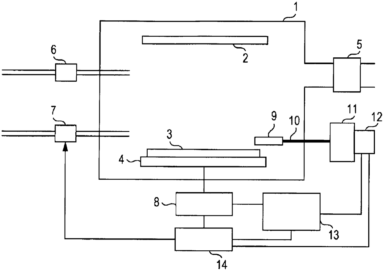
[0033] Refer below figure 1 Example 1 is described. The reactive sputtering device was constructed as follows.

[0034] The volume of the vacuum chamber: width 450mm x depth 450mm x height 500mm

[0035] Discharge mechanism: turbomolecular pump, dry pump

[0036] Power supply: DC pulse power supply

[0037] Target shape: diameter φ8 inches × thickness 5mm

[0038] Target material: Si

[0039] Inert gas: Ar

[0040] Reactive gas: O 2

[0041] Achievable pressure: 1×10 -5 Pa

[0042] A reactive sputtering device according to this example is described. A lens constituting a substrate 2 , a Si target 3 supplying a deposition material, and a cathode 4 electrically connected to the target 3 are arranged inside the vacuum chamber 1 . Ar gas and oxygen are introduced into the vacuum chamber 1 through a mass flow controller 6 that controls the amount of introduced Ar gas and through a mass flow controller 7 that controls the amount of introduced oxygen. These gases are disc...

example 2

[0053] In Example 1, the specified values ​​for the PEM control monitor values ​​are updated by taking data obtained during the previous deposition, while in Example 2, the values ​​for The specified value of the PEM control monitor value.

[0054] The device configuration and processing flow are the same as in Example 1. A method of updating a specified value for a PEM control monitor value according to a feature of this example is described. Image 6 Indicates the initial PEM control monitoring value I measured in the preliminary measurement p and V / V at this time c The relationship between. The deposition was repeated three times, and the specified values ​​for the PEM control monitoring values ​​were updated by the method used in Example 1. In this example 2, according to each of the most recent plurality of depositions, the control unit 14 obtains the plasma emission intensity during the process from the compound mode through the transfer mode to the metal mode measur...


PUM


Abstract

A reactive sputtering apparatus performs deposition in any of compound, transition, and metallic modes by employing a target and reactive gas, wherein the reactive sputtering apparatus includes an inert-gas feeding unit, a reactive-gas feeding unit, a power supply unit to supply electric power to the target, a detection unit to detect plasma emission generated upon supply of the electric power tothe target, and a control unit to adjust a reactive-gas flow rate to maintain, at a designated value, plasma emission intensity at a wavelength or a value calculated from plasma emission intensities at plural wavelengths, and wherein the control unit controls the designated value for the plasma emission intensity or the calculated value thereof such that a ratio V / Vc of a cathode voltage V in thetransition mode to Vc in the compound mode comes closer to a preset value, those voltages being detected during the deposition.

Description

technical field [0001] The present disclosure relates to a reactive sputtering device and a reactive sputtering method. Background technique [0002] A reactive sputtering process is known as a deposition method. In the reactive sputtering process, a compound film is formed on a deposition substrate by utilizing a sputtering phenomenon of a target material while introducing a reactive gas. For example, in the case of forming an oxide film, an oxide film is formed on a deposition substrate by generating a discharge under introduction of an inert gas such as Ar and oxygen and causing sputtering of a target material. [0003] Reactive sputtering is classified into three modes in which the deposition rate and film quality differ depending on the surface state of the target during film formation. These modes are generally referred to as metal mode, transition mode, and compound mode, and correspond to three different states. It is known that three states in reactive sputtering...

Claims


Application Information

Patent Timeline
IPC IPC(8): C23C14/34
CPCC23C14/0036C23C14/0042
Inventor 广木珠代
Owner CANON KK
Features
  • R&D
  • Intellectual Property
  • Life Sciences
  • Materials
  • Tech Scout
  • Unparalleled Data Quality
  • Higher Quality Content
  • 60% Fewer Hallucinations
Learn More