
Semi-automatic tool for intelligent welding of connection section of belt A type coal feeder

A semi-automatic, connecting section technology, used in welding equipment, auxiliary welding equipment, welding/cutting auxiliary equipment, etc., can solve the problems of position tolerance, scribing, inconvenient handling, and large connecting section.

Active Publication Date: 2018-09-28
新昌县北联建筑工程有限公司
View PDF6 Cites 10 Cited by
  • Summary
  • Abstract
  • Description
  • Claims
  • Application Information

AI Technical Summary

Problems solved by technology

The volume of the connecting section is relatively large, and after welding, a drilling machine with a larger specification is required to complete the drilling. It is inconvenient to mark and carry, and the large-sized drilling machine takes up more funds. If there is an error in the middle link, the entire connection will be damaged. Sections must be scrapped, resulting in large losses
If a hole is drilled on the workpiece before welding, a small-sized drilling machine is required to complete it. However, due to welding deformation, the final product of the joint section often cannot effectively guarantee the positional tolerance of the hole.
[0005] Welding is labor-intensive, and manual assembly is difficult to ensure the accuracy of shape and position tolerances
Workers who need professional training and long-term practice can complete the precise welding task, which requires high skills for workers, and similarly, the wage cost of highly skilled workers is also high

Method used


Image

  • Semi-automatic tool for intelligent welding of connection section of belt A type coal feeder
  • Semi-automatic tool for intelligent welding of connection section of belt A type coal feeder
  • Semi-automatic tool for intelligent welding of connection section of belt A type coal feeder

Examples


Embodiment

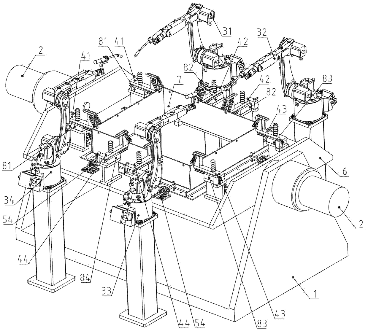
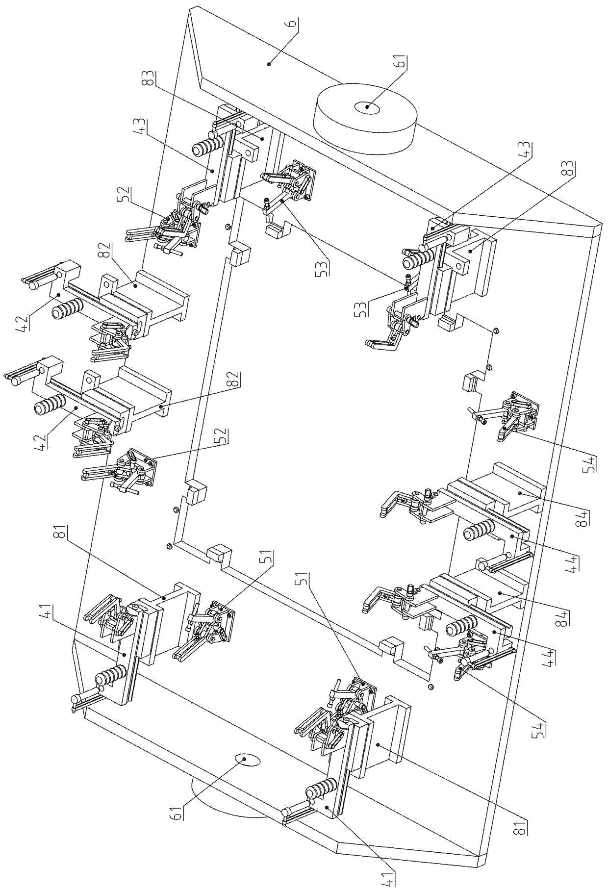
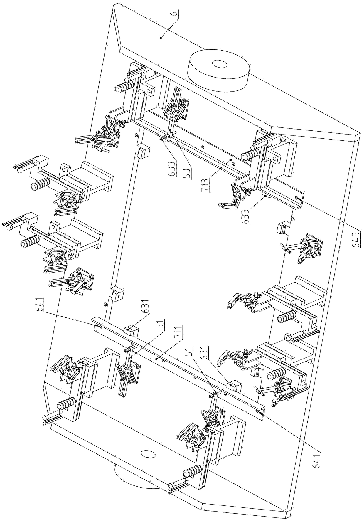
[0048] Example: see Figure 1 to Figure 20 .

[0049] An intelligent welding semi-automatic tool for the joint section of a belt coal machine, including four welding robots and semi-automatic tool;

[0050] The four welding robots are welding robot one 31, welding robot two 32, welding robot three 33 and welding robot four 34, wherein welding robot one 31 and welding robot two 32 are fixed on the front of the semi-automatic tooling, welding robot three 33 and welding robot Four 34 are fixed on the rear of the semi-automatic tooling, welding robot one 31 is on the left side of welding robot two 32, and welding robot three 33 is on the left side of welding robot four 34;

[0051]The semi-automatic tooling includes a tooling bracket 1, a combination of a servo motor and a reducer 2, and an overturning assembly; the overturning assembly includes a turntable assembly 6, a positioning assembly, a fast clamp and a base assembly; the turntable assembly 6 includes a rectangular horizo...


PUM


Abstract

The invention belongs to the technical field of mechanical coal manufacturing equipment and relates to a semi-automatic tool for intelligent welding of a connection section of a belt A type coal feeder. Lower mounting holes in the two ends of angle steel are matched with two positioning pins; pressing quick pincers are used for pressing the angle steel; a steel plate is placed on a raising surfaceof a positioning block; a first side surface clings to a positioning surface of the positioning block; a second side surface clings to a positioning surface of the steel plate and an upright side ofthe angle steel; vertical plate positioning pins are correspondingly inserted into two upper mounting holes in the two ends; and wrenching quick pincers are used for wrenching the first side surface.According to the semi-automatic tool provided by the invention, a small work piece is firstly drilled before welding, the specification of drilling equipment is reduced, fund occupation quantity is reduced, and the small work piece is convenient to transfer and operate; precise positioning is realized; the location degree tolerance of a finished fixing hole is guaranteed by virtue of the precisionof the tool; the welding deformation degree can be reduced as far as possible by virtue of symmetric welding; the workload of a worker is greatly reduced; the dependence on skills of the worker is reduced; and the labor cost is lowered.

Description

technical field [0001] The invention belongs to the technical field of coal machinery manufacturing equipment, and relates to a manufacturing equipment for a coal machine with a belt, in particular to a semi-automatic tooling for intelligent welding of the connecting section of a belt with a coal machine. Background technique [0002] The A-belt coal machine, also called the A-belt feeder, is manufactured according to the Chinese utility model patent No. 99201790.4 and named "A-belt feeder". It is used for feeding the silo of the coal system. A connecting section is provided, and the lower end of the connecting section is fixedly connected to the material guide trough, and a closed nail belt is set at the bottom of the material guide groove, and the nail belt is driven by a driving roller at one end, and a redirection roller is set at the other end, and several groups of supporting rollers are set in the middle to support the nail belt , There is a closed adhesive tape insid...

Claims


Application Information

Patent Timeline
IPC IPC(8): B23K37/00B23K37/04B23P23/04
CPCB23K37/00B23K37/0443B23P23/04
Inventor 不公告发明人
Owner 新昌县北联建筑工程有限公司
Learn More