Torque self-balancing three-ducted-fan bionic aircraft
A bionic aircraft and ducted fan technology, applied in the field of torque self-balancing three-ducted fan bionic aircraft, can solve problems such as difficult to ensure torque balance, inability to ensure the safety of people on board, high cost, etc., to suppress flight aerodynamic noise, improve Flight stability and the effect of improving flight safety
- Summary
- Abstract
- Description
- Claims
- Application Information
AI Technical Summary
Problems solved by technology
Method used
Image
Examples
Embodiment 1
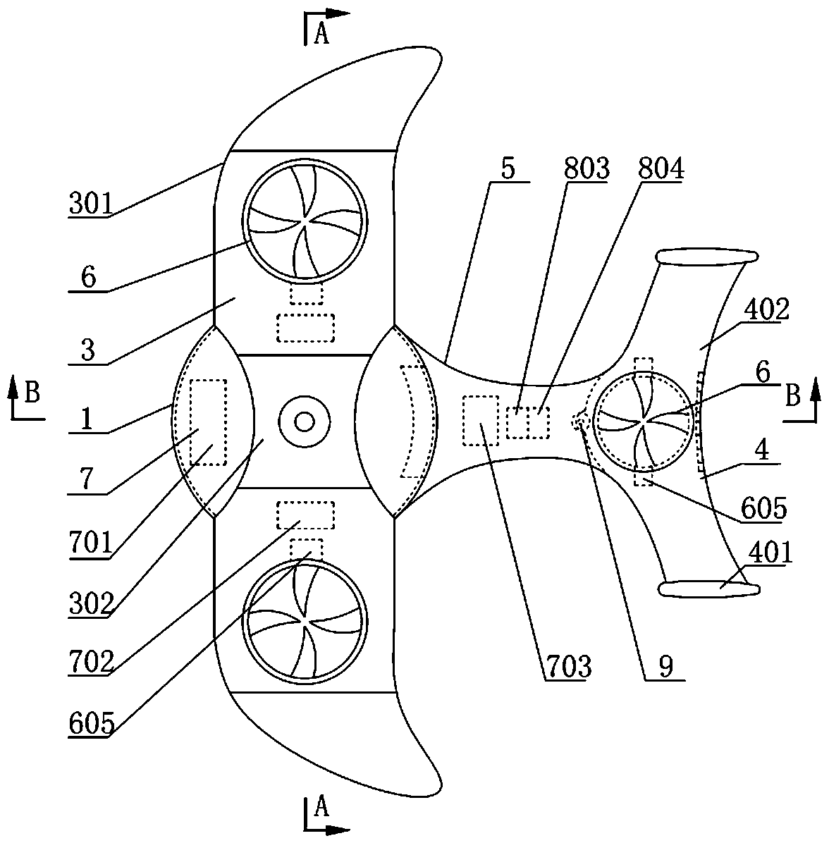
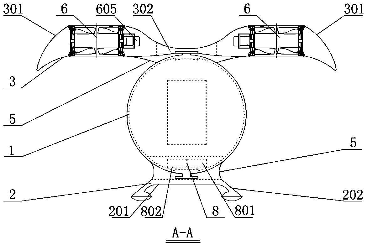
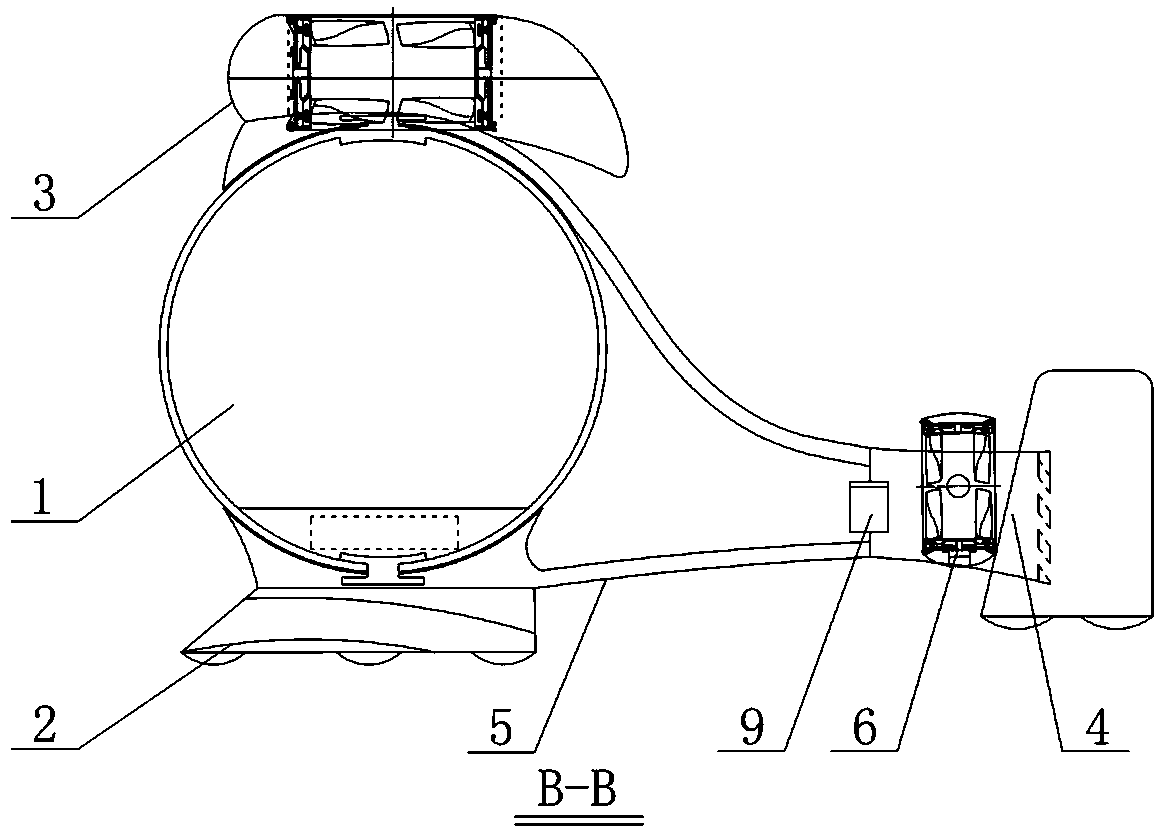
[0039] refer to figure 1 , figure 2 , image 3 , Figure 4 and Figure 5 , a torque self-balancing three-ducted fan bionic aircraft, mainly including a spherical manned cabin 1, a flight lift floor 2, a bionic wing 3, a bionic empennage 4, a transition frame 5, and three sets of self-balancing ducted fans / blades Device 6, safety protection system 7 and electric power automatic control system 8, the top and the bottom of described rotatable spherical manned cabin 1 are all connected with the front end of transition frame 5, the front end of described bionic empennage 4 is connected with the front end of transition frame 5 The rear end is connected; the bionic wing 3 is fixed on the top of the transition frame 5, and the flight lift floor 2 is fixed on the bottom of the transition frame 5; two of the self-balancing ducted fan / blade devices 6 One group is fixed on the bionic wing 3, and is symmetrically located on both sides of the spherical manned cabin 1, and the other gro...
Embodiment 2
[0048] refer to Image 6 , Figure 7 with Figure 8 , a torque self-balancing three-duct fan bionic aircraft, the main difference from Embodiment 1 is that the flight lift floor 2 of this embodiment is fixedly connected to the bottom of the transition frame 5 and forms an integral body with the bottom surface of the bionic empennage 4 to form a complete Streamlined lift floor. The bionic empennage 4 is fixedly connected to the transition frame 5, and the streamlined skin on the top of the transition frame 5 and the top surface of the horizontal empennage 402 of the bionic empennage 4 form the streamlined top surface of the aircraft. The two airfoil bodies 301 of the bionic wing 3 are arranged symmetrically at both ends of the connecting seat 302 , and the airfoil bodies 301 can rotate around the ends of the connecting seat 302 . For the two groups of self-balancing ducted fan / blade devices arranged on the bionic wing 3, the two groups of self-balancing ducted fan / blade devi...
Embodiment 3
[0050] The difference between this embodiment and Embodiment 1 is: the spherical manned cabin 1 of this implementation adopts a football-shaped manned cabin; for two groups of self-balancing duct fan / blade devices 6 arranged on the bionic wing 3, One end of the swing mechanism 603 of the self-balancing ducted fan / blade device 6 is fixed on the duct tube frame 602, and the other end is connected with the power output shaft of the swing power mechanism 605 through the airfoil body 301 of the bionic wing 3. The power mechanism 605 is fixed on the connecting seat 302 of the bionic wing 3 , and can drive the airfoil body 301 to rotate around the power output shaft of the swing power mechanism 605 . In this embodiment, the torque self-balancing fan / blade adopts a shaft ducted fan / blade with torque self-balancing. All the other are with embodiment 1.
PUM
 Abstract
Description
Claims
Application Information
 - R&D
- Intellectual Property
- Life Sciences
- Materials
- Tech Scout
- Unparalleled Data Quality
- Higher Quality Content
- 60% Fewer Hallucinations
Browse by: Latest US Patents, China's latest patents, Technical Efficacy Thesaurus, Application Domain, Technology Topic, Popular Technical Reports.
© 2025 PatSnap. All rights reserved.Legal|Privacy policy|Modern Slavery Act Transparency Statement|Sitemap|About US| Contact US: help@patsnap.com


