Eureka AIR delivers breakthrough ideas for toughest innovation challenges, trusted by R&D personnel around the world.

A permanent magnet Hall thruster outer magnetic pole structure that changes the distribution of the cathode magnetic field

A Hall thruster and magnetic field distribution technology, which is applied in the direction of thrust reverser, machine/engine, and utilization of plasma, can solve the problems of thruster performance degradation, acceleration voltage reduction, and cathode thruster coupling voltage, etc., to achieve Performance-enhancing effects

Active Publication Date: 2019-08-06
HARBIN INST OF TECH
View PDF4 Cites 0 Cited by
  • Summary
  • Abstract
  • Description
  • Claims
  • Application Information

AI Technical Summary

Problems solved by technology

The cathode of the general permanent magnet Hall thruster is located outside the magnetic interface, and the electrons emitted by the cathode must pass through the strong magnetic field area and a large number of magnetic field lines to enter the discharge channel to participate in the impact ionization process, resulting in a large coupling voltage between the cathode thrusters. The acceleration voltage is reduced, and the performance of the thruster is reduced

Method used


Image

  • A permanent magnet Hall thruster outer magnetic pole structure that changes the distribution of the cathode magnetic field
  • A permanent magnet Hall thruster outer magnetic pole structure that changes the distribution of the cathode magnetic field
  • A permanent magnet Hall thruster outer magnetic pole structure that changes the distribution of the cathode magnetic field

Examples


Embodiment Construction

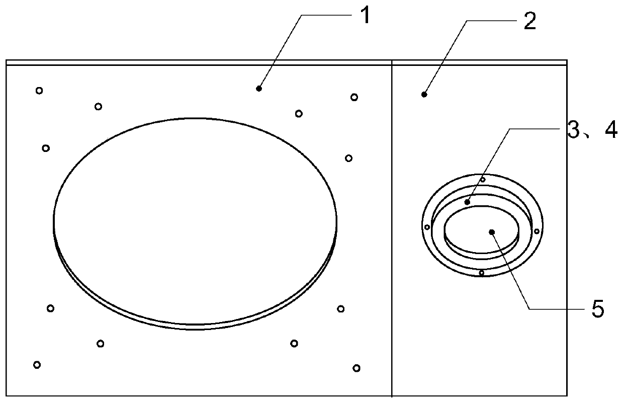
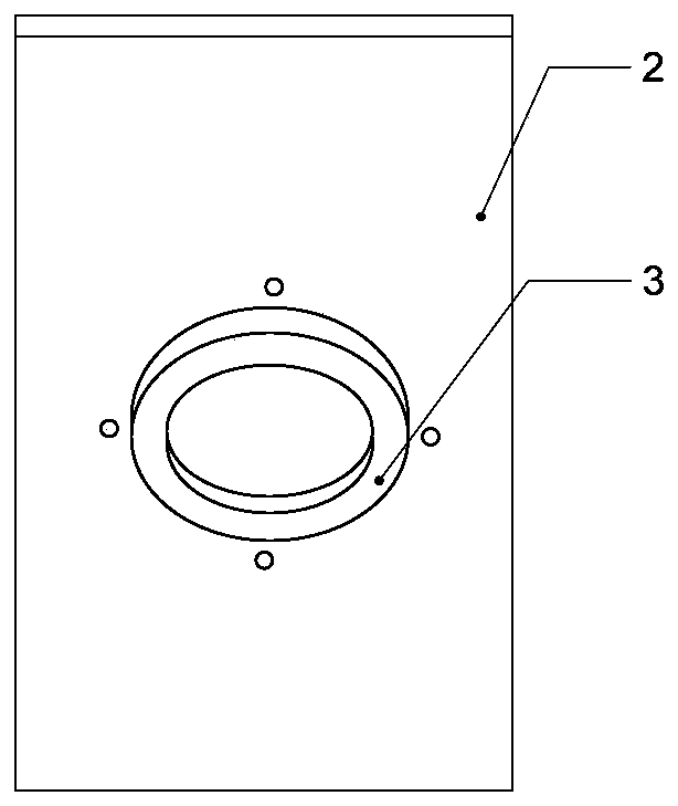
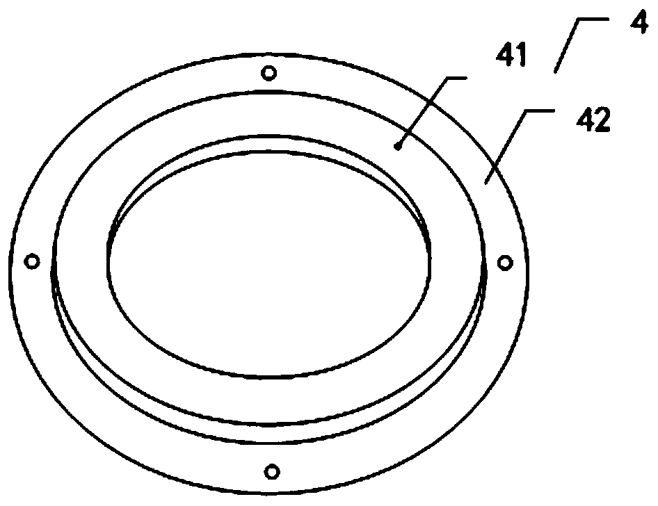
[0027] It should be noted that, in the case of no conflict, the embodiments of the present invention and the features in the embodiments can be combined with each other.

[0028] The present invention will be described in detail below with reference to the accompanying drawings and examples.

[0029] Such as Figure 1-Figure 3 As shown, a permanent magnet Hall thruster external magnetic pole structure that changes the distribution of the cathode magnetic field includes an external magnetic pole 1, an extended external magnetic pole 2, an additional permanent magnet that changes the magnetic field at the position of the cathode and moves the magnetic interface outward, and an additional permanent magnet. The magnet cover plate, the expanded outer magnetic pole 2 is fixedly arranged on one side of the outer magnetic pole 1, the expanded outer magnetic pole 2 is provided with a cathode hole 5, the size of the cathode hole 5 is larger than the diameter of the cathode, and the addi...


PUM


Abstract

The present invention provides an external magnetic pole structure of a permanent magnet Hall thruster that changes the distribution of the cathode magnetic field, including an external magnetic pole, an extended external magnetic pole, an additional permanent magnet that changes the magnetic field at the position of the cathode and moves the magnetic interface outward, and an additional permanent magnet The cover plate, the expanded outer magnetic pole is fixedly arranged on one side of the outer magnetic pole, the expanded outer magnetic pole is provided with a cathode hole, the size of the cathode hole is larger than the diameter of the cathode, and the additional permanent magnet is arranged outside the expanded On the side of the non-plume area of ​​the Hall thruster on the magnetic pole, the additional permanent magnet is fixed on the expanded outer magnetic pole through the additional permanent magnet cover plate, and the material of the expanded outer magnetic pole is a non-magnetic metal material, so The polar direction of the additional permanent magnet described above is the same as that of the outer permanent magnet column. The outer magnetic pole structure of the permanent magnet Hall thruster that changes the magnetic field distribution of the cathode according to the present invention changes the magnetic field distribution near the cathode and optimizes the conduction process of electrons into the channel.

Description

technical field [0001] The invention belongs to the fields of aerospace technology and plasma propulsion technology, and in particular relates to an outer magnetic pole structure of a permanent magnet Hall thruster which changes the distribution of a cathode magnetic field. Background technique [0002] The Hall thruster is a kind of electric thruster that uses a magnetic field to confine electrons, collides with neutral gas to ionize, and then accelerates the ions out under the action of an electric field to obtain thrust. It has the characteristics of simple structure, high specific impulse, high reliability and long in-orbit service time. It is suitable for various spacecraft position maintenance, orbit correction and transfer, space exploration and interstellar navigation. It is currently the most widely used in the world. One of a wide range of space electric propulsion units. [0003] The magnetic field is the main factor for the Hall thruster to generate and confine ...

Claims


Application Information

Patent Timeline
Patent Type & Authority Patents(China)
IPC IPC(8): F03H1/00
CPCF03H1/0006
Inventor 丁永杰李鸿魏立秋于达仁
Owner HARBIN INST OF TECH
Why Eureka
Eureka Blog
Learn More