

Delayed falling type solid particle heat absorber for solar thermal power generation
A technology for solar thermal power generation and solid particles, which is applied in the directions of solar thermal power generation, solar thermal collectors, and components of solar thermal collectors, etc., can solve the problems of increasing the residence time of particle radiation, blocking the flow of solid particles, and complex manufacturing methods. , to achieve the effects of controllable flow trajectory, efficient absorption and simple structure
- Summary
- Abstract
- Description
- Claims
- Application Information
AI Technical Summary
Problems solved by technology
Method used
Image

Examples
Embodiment Construction
[0048] The present invention will be further described below in conjunction with the accompanying drawings and specific embodiments.
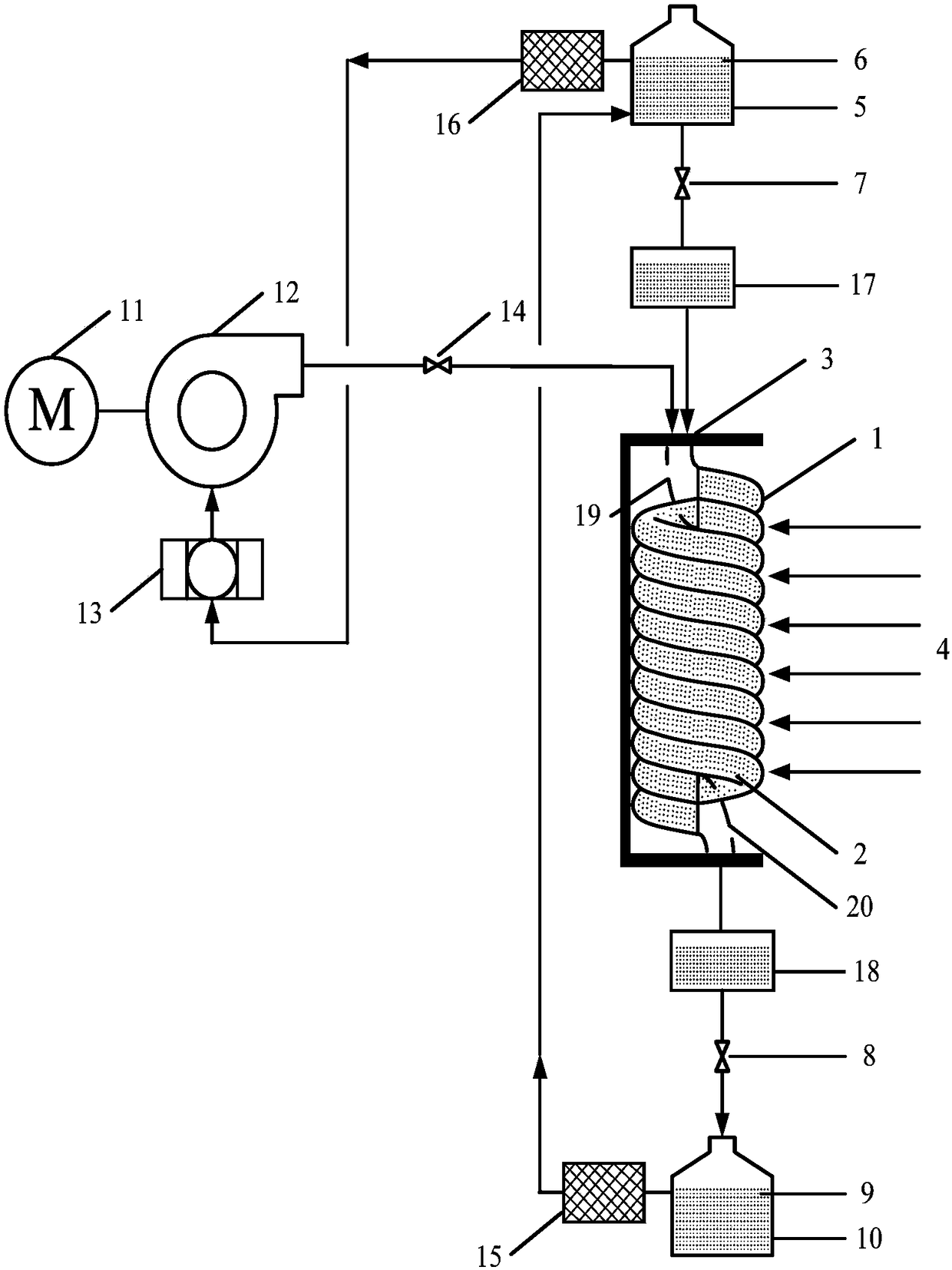
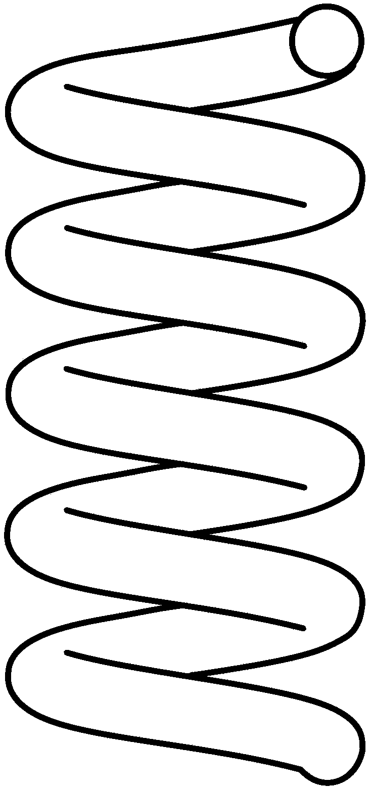
[0049] Such as figure 1 As shown, the falling-delayed solid particle heat absorber of the present invention includes a spiral quartz glass tube assembly 1, solid particles 2, an outer insulation layer 3, a low-temperature particle storage tank 5, a low-temperature particle storage tank outlet valve 7, and a high-temperature particle storage tank inlet Valve 8, high-temperature particle storage tank 10, motor 11, ventilator 12, air filter 13, main airflow regulating valve 14, high-temperature particle storage tank outlet circuit airflow metal filter 15, low-temperature particle storage tank outlet circuit airflow metal filter 16 , particle distributor 17, particle collector 18, inlet diversion section 19 and outlet diversion section 20. Solid particles 2 are contained in a helical quartz glass tube assembly 1 . The outer thermal insulation lay...
PUM
 Abstract
Description
Claims
Application Information