Constant-temperature constant-humidity environment wear resistant test tank

A constant temperature and humidity, wear-resistant test technology, applied in the direction of testing wear resistance, measuring devices, instruments, etc., can solve the problems that the pressure cannot be kept constant, there are differences, and the running speed is not high

Pending Publication Date: 2018-09-28
SHANGHAI SIIC TRANSPORTATION ELECTRIC
View PDF0 Cites 1 Cited by
  • Summary
  • Abstract
  • Description
  • Claims
  • Application Information

AI Technical Summary

Problems solved by technology

In the existing wear-resistant test equipment in the market, the driving part generally adopts the screw transmission structure, which is used to drive the test body that needs reciprocating motion. This structure has several disadvantages: 1. The running distance of the material is relatively short, generally only running 100mm Left and right (if the screw is too long, the middle part of the screw will be bent and deformed after being stressed, and the pressure during operation cannot be guaranteed); 2. The running speed is not high, and the linear speed is difficult to exceed 80mm / s, which cannot meet the needs of automotive glass lifting The running speed of the device: 60mm / s~160mm / s; 3. Some electronic components and moving mechanisms in the equipment are difficult to withstand the high temperature and high humidity working environment; only the evaluation and comparison of the wear resistance at room temperature of the material can be completed. Unable to perform tests under high temperature and high humidity environment
However, the wear resistance of many non-metallic materials does not change linearly under different temperature and humidity environments, so it is necessary to evaluate the wear resistance of materials in different temperature ranges and different humidity environments; 4. Test pieces A single movement stroke is only about 100mm, while most automotive window regulators have a single movement stroke of 400mm to 550mm, and the distance of a single movement needs to be achieved by reciprocating 4 to 5 times of the test piece; the test piece is in the test process. Wear powder will be produced, and these powders will participate in the friction test. This test method is equivalent to the cumulative number of cycles of forward and reverse friction of two test pieces in a short distance, which is different from the actual working state of the part. The amount of wear is different from the actual working state

Method used


Image

  • Constant-temperature constant-humidity environment wear resistant test tank
  • Constant-temperature constant-humidity environment wear resistant test tank
  • Constant-temperature constant-humidity environment wear resistant test tank

Examples


Embodiment Construction

[0032] Below in conjunction with accompanying drawing and embodiment the present invention will be further described

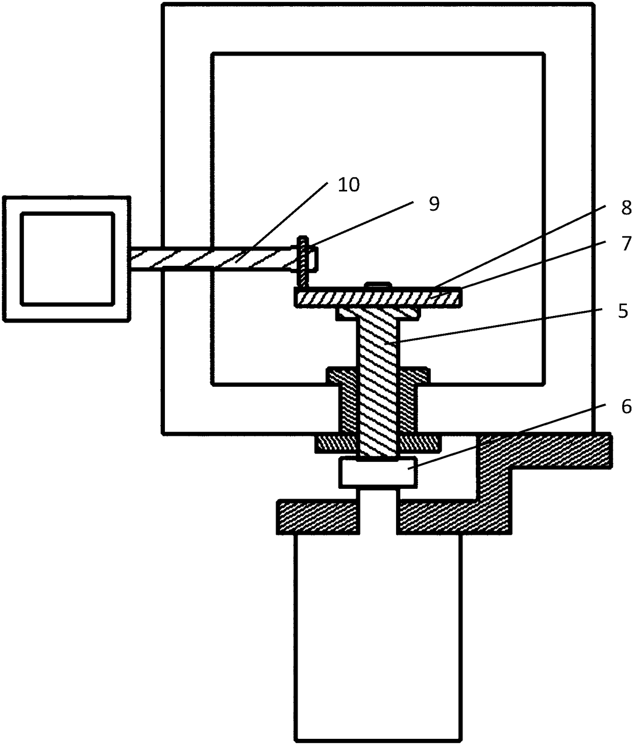
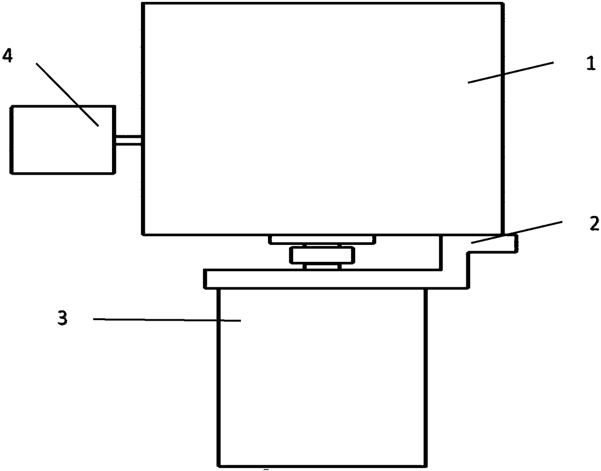
[0033] The main body of the present invention is a constant temperature and humidity environment wear-resisting test box (as attached figure 2 , 3 shown). There is a disc-shaped driving disc 7 with a diameter of 200mm inside the box body 1. One of the materials to be tested is processed into a disc-shaped disc body 8, which is fixed on the driving disc 7 by two screws with disc-shaped gaskets. The lower end of the driving disc 7 is fixed to the driving shaft 5, the driving shaft 5 protrudes out of the casing, the casing 1 is equipped with a flange, and a sealing ring is arranged between the flange and the driving shaft 5 for fixing the driving shaft 5 and sealing effect . The lower part of the box body 1 has a motor fixing bracket 2, which fixes the drive motor 3 on the box body 1, and keeps the motor shaft and the drive shaft 5 in a coaxial state, and the...


PUM

PropertyMeasurementUnit
radiusaaaaaaaaaa

Abstract

The invention relates to a constant-temperature constant-humidity environment wear resistant test tank, and concretely relates to the constant-temperature constant-humidity environment wear resistanttest tank, which relates to the technical field of wear resistant testing. The wear resistant test box comprises a tank body (1), a driving motor (3) outside the tank body (1), a driving motor fixed support (2), and an electrical equipment control tank (4); the tank body (1) has sealed constant-temperature constant-humidity environment, wherein a driving shaft (5) is arranged in the tank body (1),the upper part of the tank body (1) is connected with a driving plate (7), a lower end of the driving shaft (5) is fixedly connected with a shaft coupling (6) stretching out of the tank body (1), theother end of the shaft coupling (6) is fixedly connected with the driving motor (3), and a clamping arm (10) used for fixing a to-be-tested material and penetrating the electrical equipment control tank (4) and the tank body (1); and a spherical or flat transverse plane of a round rod-shaped material (9) and a disk material (8) are relatively perpendicular contacted. The wear resistant test tankis suitable for rapidly testing wear resistant performance of machinery part materials such as automobile parts under humiture environments.

Description

technical field [0001] The invention relates to the technical field of wear-resistant testing, and specifically refers to a constant-temperature and constant-humidity environment wear-resistant test chamber, which is suitable for rapid testing of the wear-resistant performance of mechanical parts materials such as automobile parts under various temperature and humidity environments. Background technique [0002] In the product structure of the automobile glass regulator, the slider carrying the automobile glass slides up and down under the constraint of the guide rail, and a relative sliding friction motion occurs between the slider and the guide rail, which will cause wear on both the slider and the guide rail. How to choose the optimal one? The material of the slider and the surface treatment material of the guide rail are a major difficulty in the design of glass regulator products. It is necessary to design a friction resistance test to compare the selected materials; if...

Claims


Application Information

Patent Timeline
Patent Type & Authority Applications(China)
IPC IPC(8): G01N3/56G01N19/02
CPCG01N3/56G01N19/02G01N2203/005G01N2203/022
Inventor 黄春田罗刚
Owner SHANGHAI SIIC TRANSPORTATION ELECTRIC
Why Eureka
Try Eureka