Dehydration treatment device of medical waste

A technology of medical waste and treatment equipment, which is applied in the field of medical waste dehydration treatment equipment, can solve problems such as environmental pollution, epidemic disease, and troublesome treatment of medical solid-liquid mixed waste, and achieve the effect of facilitating subsequent treatment and improving the treatment effect

Pending Publication Date: 2018-10-09
范宝峰
View PDF6 Cites 8 Cited by
  • Summary
  • Abstract
  • Description
  • Claims
  • Application Information

AI Technical Summary

Problems solved by technology

If it is not handled properly, it will cause serious pollution to the environment and may also become the source of epidemics
The medical waste in hospitals includes solid waste, liquid waste and solid-liquid mixed waste, etc. General solid waste treatment is relatively easy; however, the treatment of medical solid-liquid mixed waste is more troublesome. In medical solid-liquid mixed waste, solid waste and Liquid waste is separated, but there is no dehydration treatment device specially used for medical solid-liquid mixed waste in the prior art

Method used


Image

  • Dehydration treatment device of medical waste
  • Dehydration treatment device of medical waste
  • Dehydration treatment device of medical waste

Examples


specific Embodiment approach 1

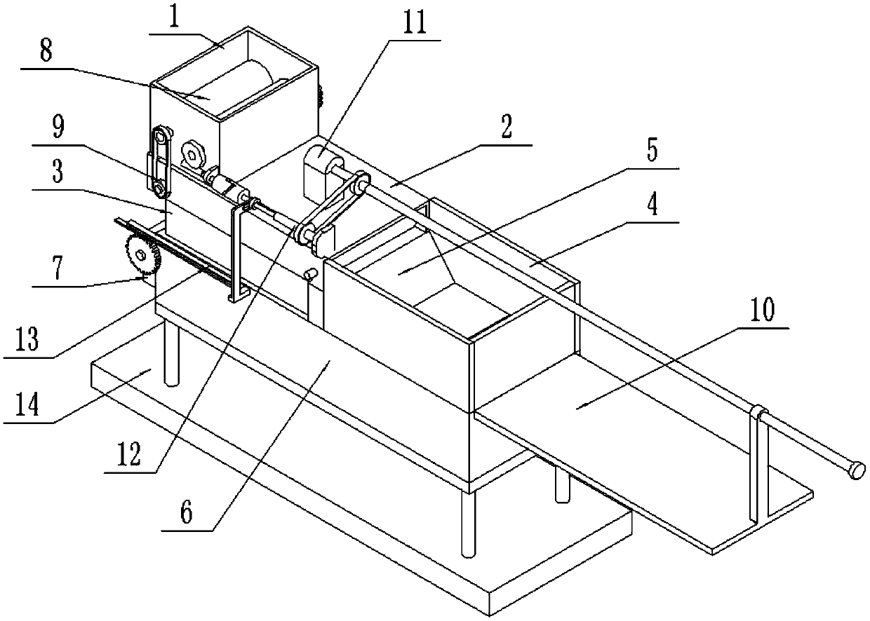
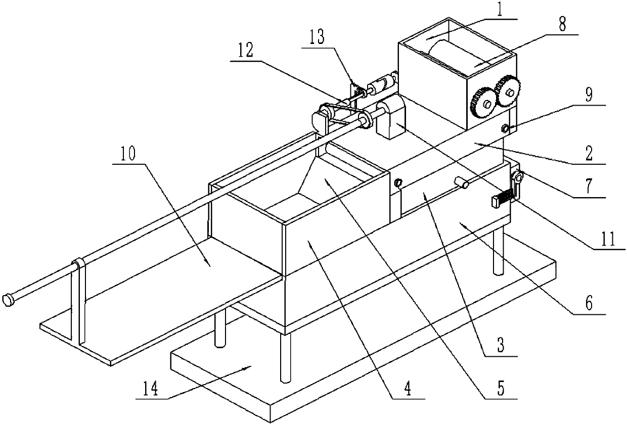
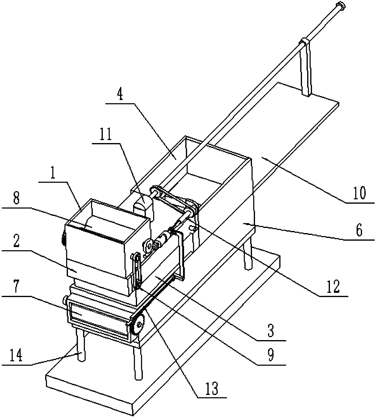
[0043] Such as Figure 1-17 As shown, a medical waste dehydration treatment device includes a waste drop box 1, a waste delivery box 2, a sewage collection box 3, a blanking box 4, a scraping plate 5, a squeeze dehydration box 6, and a discharge door assembly 7 , a waste pretreatment device 8, a waste conveying and dehydrating device 9, a waste squeezing and dehydrating device 10, a drive control device 11, a drive wheel assembly 12, a feed control assembly 13 and a support frame 14, and the waste drop box 1 The lower end is fixedly connected and connected to the waste delivery box 2; the bottom surface of the waste delivery box 2 is provided with a drain hole, the top surface of the sewage collection box 3 is hollowed out, and the sewage collection box 3 is fixedly connected to the waste delivery box 2 The lower end of the sewage collection box 3 communicates with the waste delivery box 2 through the drain hole; the rear end of the waste delivery box 2 is fixedly connected an...

specific Embodiment approach 2

[0046] Such as Figure 1-17 As shown, the drive control device 11 includes a drive motor 11-1, a drive shaft 11-2 and a drive pulley 11-3; the output shaft of the drive motor 11-1 is connected to the drive shaft 11-2 through a coupling; The driving shaft 11-2 is fixedly connected to the driving pulley 11-3; the driving motor 11-1 is fixedly connected to the waste transport box 2 through the motor base; The material extrusion dehydration device 10; the drive pulley 11-3 is connected to the drive wheel assembly 12 through a belt. When the drive control device 11 is in use, after the drive motor 11-1 is connected to the power supply and turned on by the control switch, the drive motor 11-1 can drive the drive shaft 11-2 to rotate, and the drive shaft 11-2 can drive the drive shaft 11-2 when it rotates. The pulley 11-3 rotates, the drive pulley 11-3 can drive the transmission wheel assembly 12 to work, and the waste extrusion dehydration device 10 can work when the drive shaft 11...

specific Embodiment approach 3

[0047] Such as Figure 1-17 As shown, the waste squeezing and dehydrating device 10 includes an externally threaded transmission shaft 10-1, a limit plate 10-2, a movable connecting plate 10-3, a falling blocking plate 10-4 and an extruding plate 10-5; One end of the externally threaded transmission shaft 10-1 is connected to the drive shaft 11-2 through a coupling, and the other end of the externally threaded transmission shaft 10-1 is threaded to the limit disc 10-2; the movable connecting plate 10-3 One end is screwed to the externally threaded transmission shaft 10-1, and the other end of the movable connecting plate 10-3 is fixedly connected to the rear end of the falling-blocking plate 10-4; On the rear side of the case 6, the front end of the falling plate 10-4 is fixedly connected to the extruding plate 10-5, and the extruding plate 10-5 is slidingly fitted and connected to the inner surface of the extruding and dehydrating case 6. When the waste extrusion dehydration...


PUM


Abstract

The invention relates to the field of medical waste treatment, in particular to a dehydration treatment device of medical waste. The device comprises a waste putting box, a waste conveying box, a waste water collecting box, a material falling box, a scraping plate, an extrusion dewatering box, a discharging door assembly, a waste pretreatment device, a waste conveying and dewatering device, a waste extrusion dehydration device, a driving control device, a transmission wheel assembly, a feeding control assembly and a supporting frame, wherein the lower end of the waste putting box is fixedly connected and communicates with the waste conveying box; and a water falling hole is formed in the bottom surface of the waste conveying box, the top surface of the waste water collecting box is hollow,and the waste water collecting box is fixedly connected to the lower end of the waste conveying box. The dehydration treatment device of the medical waste can be used for carrying out dehydration treatment on solid-liquid mixed medical waste containing liquid so that solid medical waste and liquid medical waste can be conveniently classified and treated, the treatment effect is improved, and thehazards of viruses and germs in the medical waste are reduced.

Description

technical field [0001] The invention relates to the field of medical waste treatment, in particular to a medical waste dehydration treatment device. Background technique [0002] According to the medical inspection report of the national health department, because medical waste has the characteristics of space pollution, acute infection and latent pollution, the harmfulness of viruses and germs is dozens, hundreds or even thousands of times that of ordinary domestic waste. If it is not handled properly, it will cause serious pollution to the environment and may also become the source of epidemics. Medical waste in hospitals includes solid waste, liquid waste, and solid-liquid mixed waste, etc. General solid waste treatment is relatively easy; however, the treatment of medical solid-liquid mixed waste is more troublesome, and medical solid-liquid mixed waste needs to be separated from solid waste Liquid waste is separated, but there is no dehydration treatment device special...

Claims


Application Information

Patent Timeline
Patent Type & Authority Applications(China)
IPC IPC(8): B30B9/20B09B3/00
CPCB09B3/00B30B9/20
Inventor 范宝峰
Owner 范宝峰
Why Eureka
Try Eureka