
Pneumatic conveying system

A pneumatic conveying system and air conveying technology, applied in conveyors, conveying bulk materials, transportation and packaging, etc., can solve the problems of high operation and maintenance costs, increased system failure points, fast conveying speed, etc. The effect of reducing equipment, improving stability and reliability, and effectively controlling conveying speed

Inactive Publication Date: 2018-10-09
FUJIAN LONGKING
View PDF6 Cites 6 Cited by
  • Summary
  • Abstract
  • Description
  • Claims
  • Application Information

AI Technical Summary

Problems solved by technology

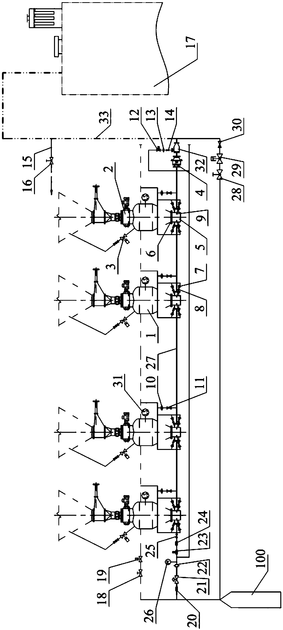
When the feeding of the warehouse pump 1 to the delivery pipeline 33 cannot be fluidized and uncontrollable, the only way to achieve smooth delivery in the delivery pipeline 33 is to increase the gas volume to ensure delivery, which will result in high energy consumption and low delivery speed. Fast, and the wear of pneumatic conveying is proportional to the third power of the conveying speed, so it has caused the wear of the conveying pipe 33, the frequent wear of the intake pipe branch connected to the mixing chamber 5 and the conveying pipe 27 between the warehouse pumps, and the air intake pipe A series of problems such as the frequent damage of the pipeline air supply check valve 11 between the warehouse and the pump on the branch road and the frequent damage of the intake check valve 8 in the mixing chamber bring great inconvenience to the operation and maintenance, and affect the safe, stable and environmentally friendly operation of the system. There are huge hidden dangers, and at the same time cause high operation and maintenance costs
[0008] At the same time, due to the large number of air intake points and various check valves and other equipment in the conveying system, as many as dozens, the system is cumbersome. In addition, under the condition of a certain amount of air to be transported, due to too many air intake points, effective distribution cannot be realized ( If the air volume is too small, the check valve cannot be opened), which will lead to a series of problems such as the uncontrollable delivery air volume within the design air volume, the increase of system failure points, and the aggravation of system wear, which further exacerbates the high energy consumption and high operation and maintenance costs of the transmission system , the system is unstable

Method used


Image

  • Pneumatic conveying system
  • Pneumatic conveying system
  • Pneumatic conveying system

Examples


Embodiment Construction

[0034] The present invention proposes a pneumatic conveying system that greatly simplifies the structure of the pneumatic conveying system through necessary transformation on the basis of the original pneumatic conveying system, improves stability and adaptability to gray samples, and realizes a pneumatic system that reduces the comprehensive air consumption of the system by more than 30%. Equipment for energy-saving transformation of conveying systems.

[0035] The following will clearly and completely describe the technical solutions in the embodiments of the present invention with reference to the accompanying drawings in the embodiments of the present invention. Obviously, the described embodiments are only some, not all, embodiments of the present invention. Based on the embodiments of the present invention, all other embodiments obtained by persons of ordinary skill in the art without making creative efforts belong to the protection scope of the present invention.

[003...


PUM


Abstract

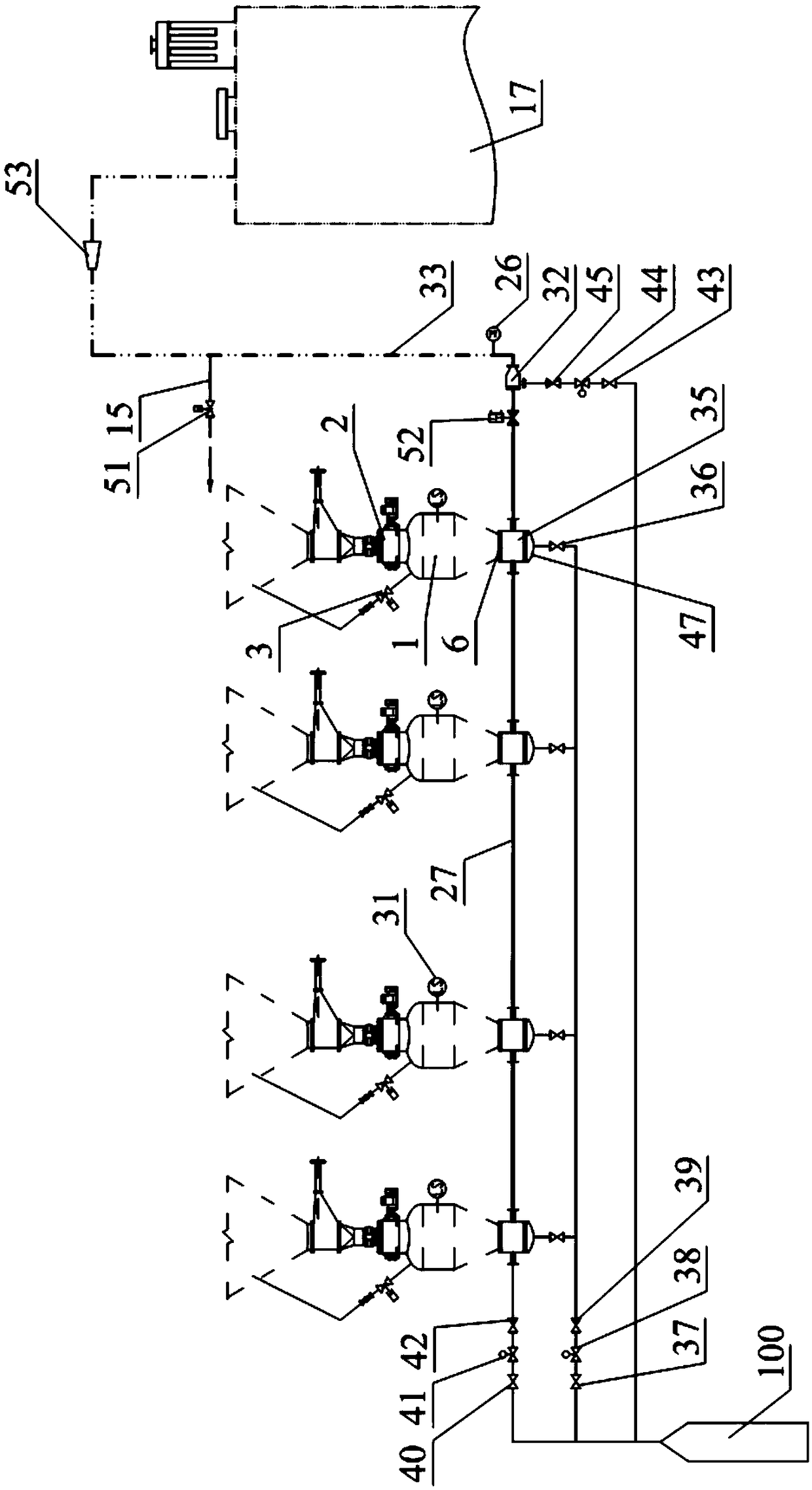
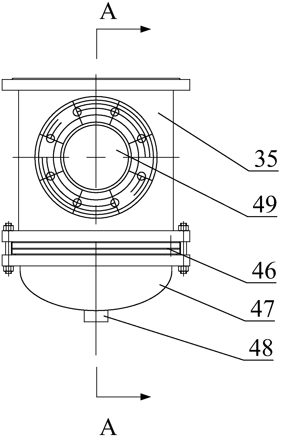
The invention discloses a pneumatic conveying system. The pneumatic conveying system comprises a compressed air conveying mother tube, one or more bin pumps which are arranged in series, a discharge valve, a discharge hole gas supplementing machine, a conveying pipeline and a terminal bin, wherein the lower end of each bin pump is connected with a fluidizing device, the fluidizing device comprisesa fluidizing room, a fluidizing disc and a fluidizing room sealing head which are sequentially connected from top to bottom, and further comprises a fluidizing room discharge tube which transverselypenetrates through the fluidizing room, a fluidizing room discharge lifting tube which longitudinally communicates with the lower portion of the fluidizing room discharge tube and is positioned abovethe fluidizing disc is arranged inside the fluidizing room. According to the scheme adopted by the invention, the compressed air conveying mother tube is re-arranged, and is divided into three gas inlet branches, namely a fluidized gas inlet branch which communicates with the fluidizing room sealing head, a conveyed gas inlet branch which is connected to the first fluidizing room discharge tube which is in series connection in a gas flow conveying direction, and an auxiliary gas-blowing gas inlet branch which communicates with the discharge hole gas supplementing machine. According to the scheme adopted by the invention, the pneumatic conveying system is greatly simplified in structure, and also can realize great reduction of comprehensive gas consumption of the system.

Description

technical field [0001] The invention relates to the technical field of pneumatic conveying systems, in particular to a pneumatic conveying system. Background technique [0002] Pneumatic conveying system has been widely used in various domestic industries due to its advantages of flexible arrangement of ash conveying pipelines and no need to consume water resources. The good and the bad are mixed. Many systems have bloated system configuration, unstable operation, and high failure rate. A series of problems such as excessively high conditions. [0003] The stable and reliable operation of the pneumatic conveying system mainly depends on two aspects: the warehouse pump and the pipeline. The warehouse pump must ensure smooth and controllable material supply, and the pipeline must ensure smooth transportation. influences. In order to ensure smooth transportation in the pipeline, in addition to determining a reasonable pipe diameter and variable diameter, the material in the ...

Claims


Application Information

Patent Timeline
Patent Type & Authority Applications(China)
IPC IPC(8): B65G53/16B65G53/58B65G53/52
CPCB65G53/16B65G53/52B65G53/58
Inventor 田青熊兴勤张进明潘仁湖
Owner FUJIAN LONGKING
Learn More