
Centrifugal sedimentation type water purifier for large sewage treatment plant

A sewage treatment plant, centrifugal sedimentation technology, applied in water/sewage multi-stage treatment, water/sludge/sewage treatment, centrifugal separation of water/sewage treatment, etc., can solve problems such as hindering sewage treatment, slow purification, discharge, etc. , to achieve the effect of reducing work efficiency, improving purification efficiency and increasing workload

Inactive Publication Date: 2018-10-09
TAIZHOU BIAOMENG INTPROP AGENCY
View PDF4 Cites 0 Cited by
  • Summary
  • Abstract
  • Description
  • Claims
  • Application Information

AI Technical Summary

Problems solved by technology

[0002] The industrial water purification device is composed of three parts: a pretreatment system, a fine treatment system, and a post-treatment system. Particulate matter), colloid, organic matter, hardness, microorganisms and other impurities are greatly reduced, and the processing load of the fine treatment system such as electrostatic desalination can be used to extend its service life. It is widely used in coal-containing wastewater, ash and slag washing wastewater, Industrial comprehensive sewage, chemical workshop wastewater, mine wastewater, hydraulic coal mining wastewater, coal washing wastewater, coking wastewater in the coal industry, beneficiation wastewater, smelting wastewater, circulating cooling water, oily wastewater in the metallurgical industry, production wastewater in ceramics, abrasives, and foundry industries , recycled papermaking wastewater, printing and dyeing wastewater, electroplating wastewater, high turbidity river water, wet dedusting water and domestic drinking water with rivers, lakes and wells as water sources. The existing sewage purifiers are high in cost and slow in purification speed, which seriously hinders The treatment of sewage has caused many enterprises to discharge a large amount of sewage. In the prior art, for example, the invention patent with application number 96243048.X includes a cylindrical main body with a conical bottom at the lower end and a concentrated mud There is a filter net layer on the upper part of the main cylinder, and the filter material is filled on the filter net layer. There is a baffle plate on the filter material, and there are multiple filter heads on the baffle plate. The water pipe interface is characterized in that there is a down-spin isolation tube at the lower part of the main cylinder, the down-spin isolation tube is cylindrical, the upper end of the down-spin isolation tube is a bell mouth, and the upper edge of the bell mouth is sealed and connected with the inner wall of the main tube, and the sewage The water inlet pipe enters the main cylinder below the connection between the downspin isolation cylinder and the main body cylinder. Although the invention has a simple structure, there are many deficiencies and defects. In the existing equipment, the design of the downspin isolation cylinder has defects. Lack of sewage cleaning and discharge devices, impurities in the mud can easily cause the blockage of the concentrated mud drain, and manual work is required to remove the blockage, which increases the workload of the operator, makes the operator prone to physical fatigue, and reduces the operator's work Efficiency increases the production and processing cost of the enterprise and causes waste of resources of the water purifier. In view of these situations, in order to avoid the above-mentioned technical problems, it is necessary to provide a method to overcome the defects in the prior art.

Method used

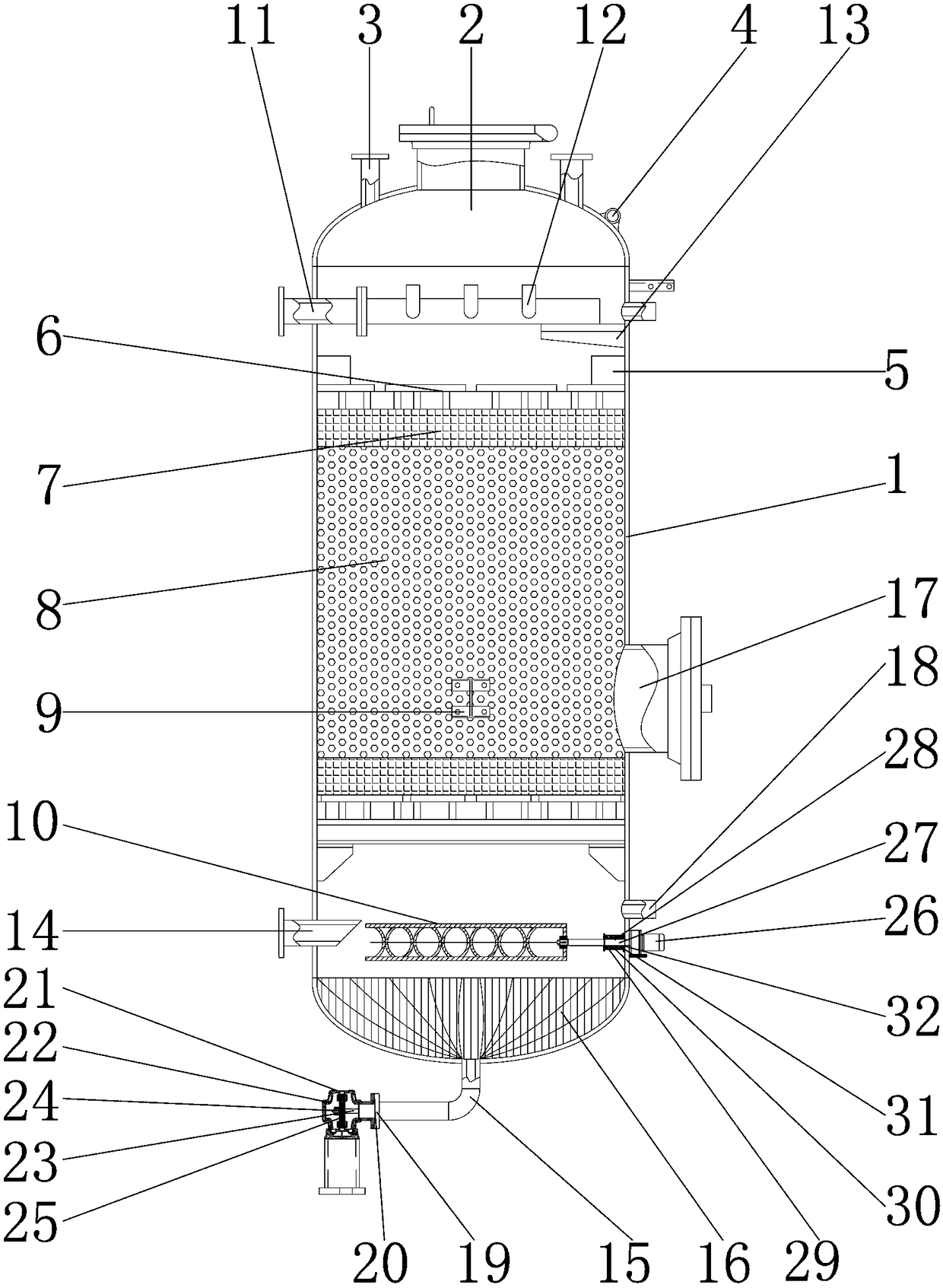
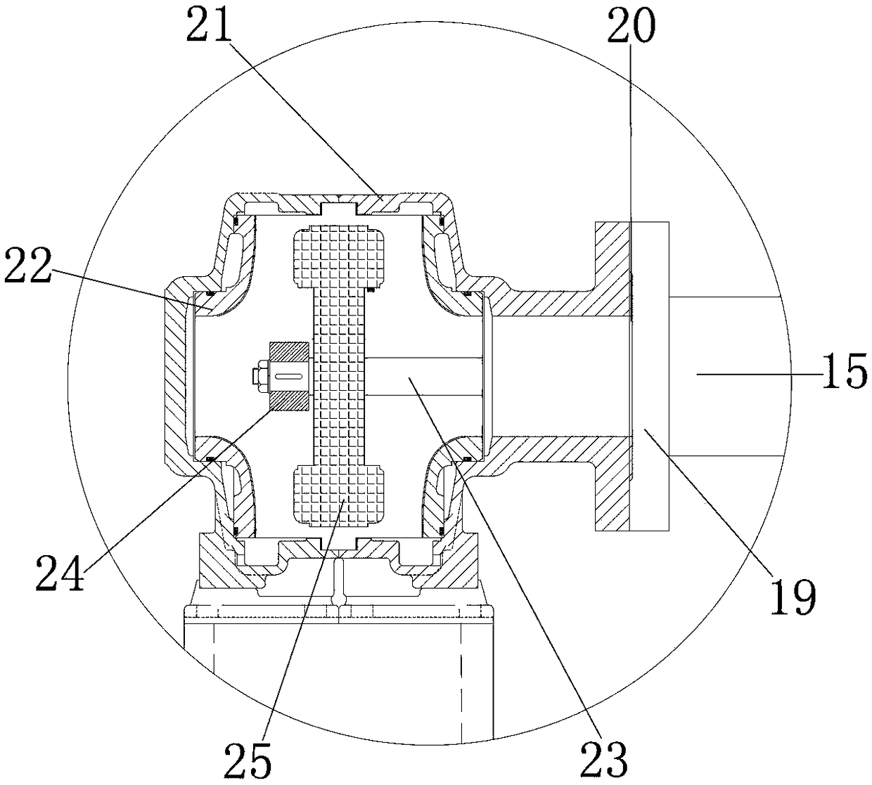
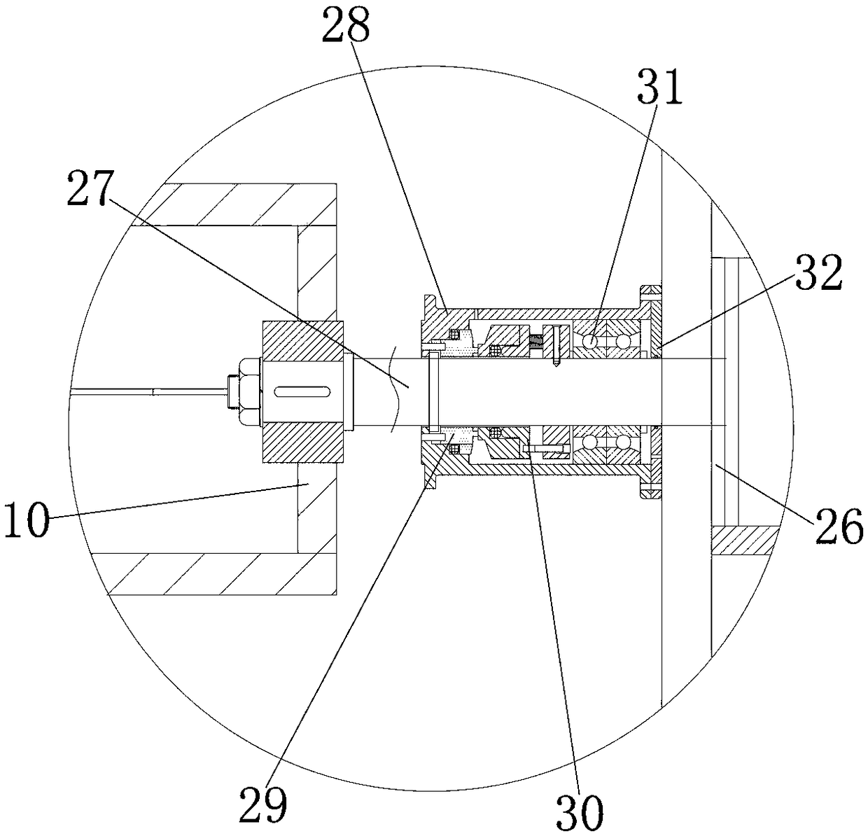

Image

  • Centrifugal sedimentation type water purifier for large sewage treatment plant
  • Centrifugal sedimentation type water purifier for large sewage treatment plant
  • Centrifugal sedimentation type water purifier for large sewage treatment plant

Examples


Embodiment Construction

[0019] The following will clearly and completely describe the technical solutions in the embodiments of the present invention with reference to the accompanying drawings in the embodiments of the present invention. Obviously, the described embodiments are only some, not all, embodiments of the present invention. Based on the embodiments of the present invention, all other embodiments obtained by persons of ordinary skill in the art without making creative efforts belong to the protection scope of the present invention.

[0020] see Figure 1-3, the present invention provides a technical solution: a centrifugal sedimentation water purifier for a large-scale sewage treatment plant, including a tank body 1 for installing and fixing a bracket 6 and a first filter screen 7, and the outer wall of the tank body 1 is installed with purpose Window 9 is used to observe the running situation in the tank body 1. The inner wall of the eye window 9 is connected with the outer wall of the ta...


PUM


Abstract

The invention discloses a centrifugal sedimentation type water purifier for a large sewage treatment plant. The centrifugal sedimentation type water purifier for the large sewage treatment plant comprises a tank, wherein a water inlet is formed in the top end of the outer wall of the tank; a ventilating opening is formed in the top end of the outer wall of the tank; the inner wall of the ventilating opening is connected with the outer wall of the tank; a support is mounted on the inner wall of the tank; the outer wall of the support is connected with the inner wall of the tank; and a clear water opening is formed above the support. According to the centrifugal sedimentation type water purifier for the large sewage treatment plant, through cooperation of the tank, a first filter screen anda second filter screen, under the effect of a backwashing opening, the tank provides good supporting and adjustment for connection between a motor and a valve body, so that sewage is fully stirred andfilter, the sewage purifying efficiency is improved, a sewage cleaning opening is prevented from being blocked by concentrated mud or sediments, the purchasing cost of a user is saved, resource wasteof the centrifugal sedimentation type water purifier for the large sewage treatment plant is avoided, and the centrifugal sedimentation type water purifier for the large sewage treatment plant is suitable for being popularized and used.

Description

technical field [0001] The invention relates to the technical field of industrial water purifiers, in particular to a centrifugal sedimentation water purifier for large sewage treatment plants. Background technique [0002] The industrial water purification device is composed of three parts: a pretreatment system, a fine treatment system, and a post-treatment system. Particulate matter), colloid, organic matter, hardness, microorganisms and other impurities are greatly reduced, and the processing load of the fine treatment system such as electrostatic desalination can be used to extend its service life. It is widely used in coal-containing wastewater, ash and slag washing wastewater, Industrial comprehensive sewage, chemical workshop wastewater, mine wastewater, hydraulic coal mining wastewater, coal washing wastewater, coking wastewater in the coal industry, beneficiation wastewater, smelting wastewater, circulating cooling water, oily wastewater in the metallurgical indust...

Claims


Application Information

Patent Timeline
Patent Type & Authority Applications(China)
IPC IPC(8): C02F9/04
CPCC02F1/001C02F1/38C02F1/52C02F9/00C02F2301/08
Inventor 宋晓贺
Owner TAIZHOU BIAOMENG INTPROP AGENCY
Learn More