
Approximate square wave Marx generator based on magnetic switch

A generator and magnetic switch technology, applied in the field of near-square-wave Marx generators, can solve the problems of increasing system complexity and increasing the probability of failure, and achieve the effect of simple structure and principle and low manufacturing cost

Inactive Publication Date: 2018-10-09
NORTHWEST INST OF NUCLEAR TECH
View PDF3 Cites 5 Cited by
  • Summary
  • Abstract
  • Description
  • Claims
  • Application Information

AI Technical Summary

Problems solved by technology

The gas switch has the characteristics of high power and strong flow capacity, but due to the nature of gas discharge, this type of switch has certain limitations in terms of life and stability, especially in the Marx generator, which requires a large amount of gas switch, resulting in a multiplied probability of failure
In addition, in order to improve the working stability of the Marx generator and reduce the output jitter, a special trigger is required to trigger the first few gas switches in the generator, which increases the complexity of the system

Method used


Image

  • Approximate square wave Marx generator based on magnetic switch
  • Approximate square wave Marx generator based on magnetic switch
  • Approximate square wave Marx generator based on magnetic switch

Examples


Embodiment 1

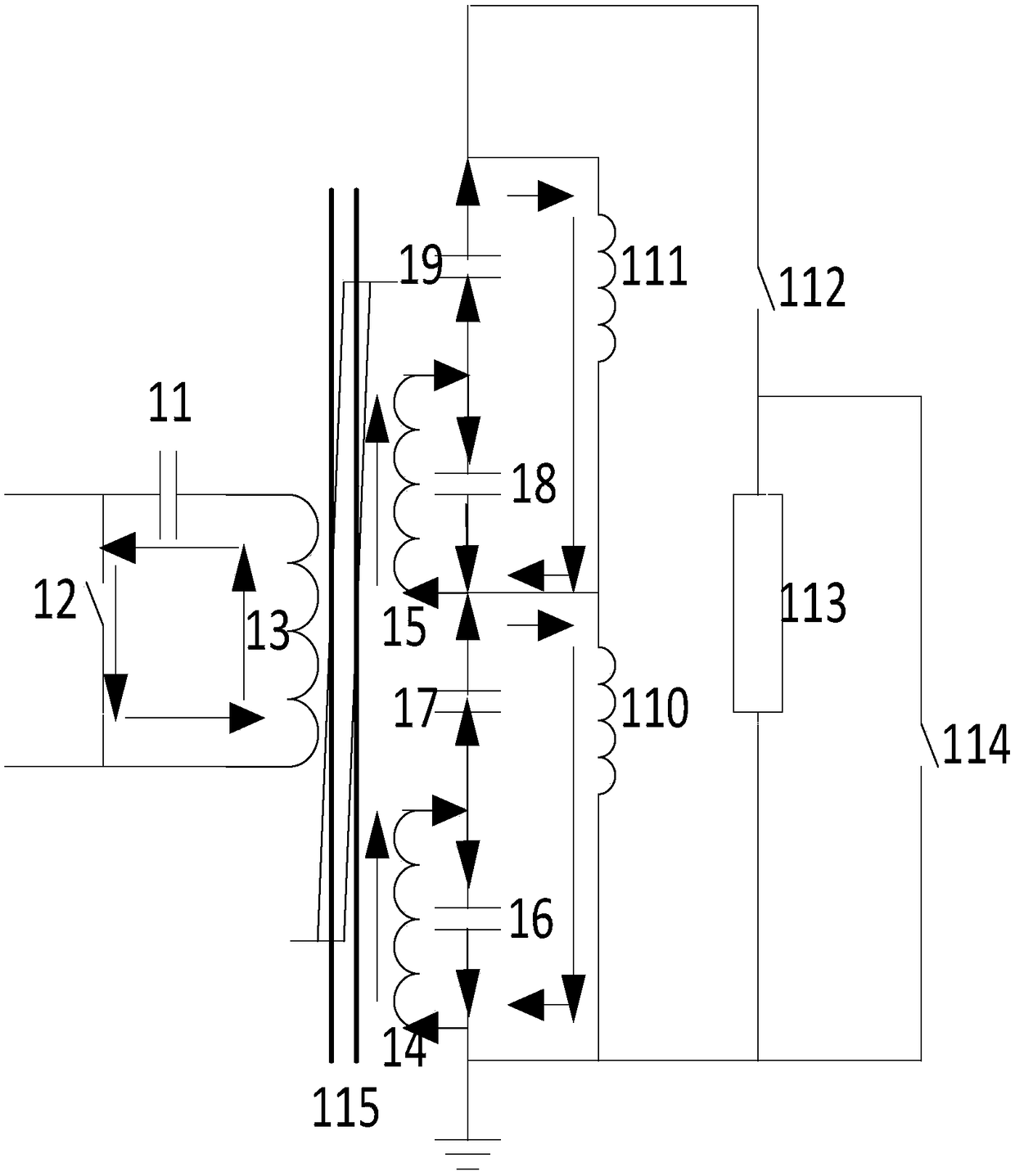
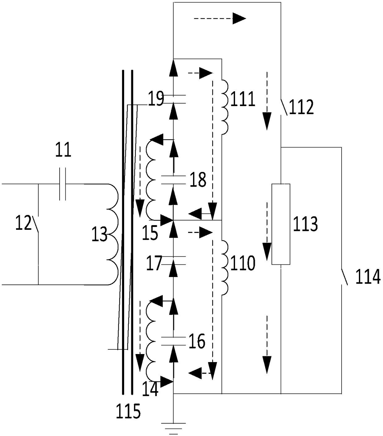
[0030] From Figure 1a and Figure 1b It can be seen that this embodiment includes four parts: a primary discharge unit, a saturable pulse transformer unit, a Marx generator unit, and a discharge unit.

[0031] The primary discharge unit is composed of a primary energy storage capacitor 11 and a primary capacitor discharge control switch 12 .

[0032] The saturable pulse transformer unit is composed of a saturable transformer primary inductance 13 , a saturable transformer secondary inductance 14 , 15 and a transformer magnetic core 115 .

[0033] The Marx generator unit is composed of adjustment capacitor 16 , secondary capacitors 17 , 18 , 19 and grounding inductance 110 , 111 . The secondary inductance 14 of the saturable transformer, the adjustment capacitor 16, the secondary capacitor 17 and the grounding inductance 110 form an adjustment unit, and the grounding inductance 110 is connected in parallel at both ends of the circuit where the adjustment capacitor 16 and the ...

Embodiment 2

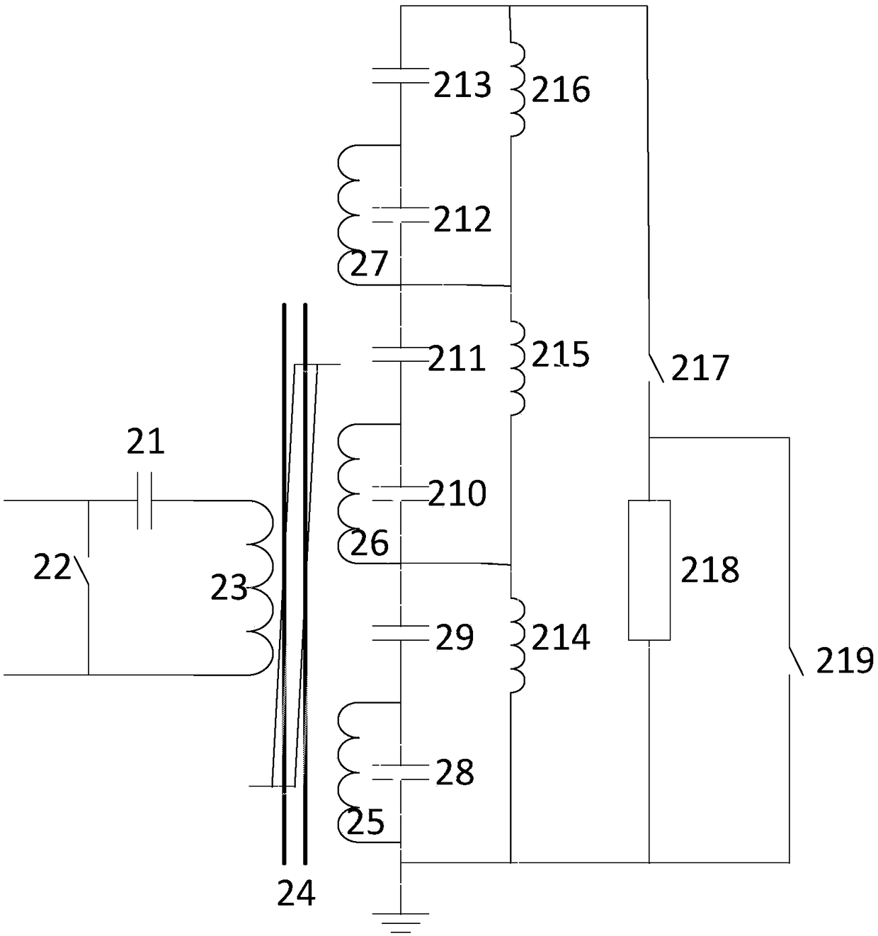
[0037] From figure 2 It can be seen that the circuit of this embodiment adopts a six-stage pulse capacitor structure. Including a primary energy storage capacitor 21, a primary capacitor discharge control switch 22, a saturable transformer primary inductance 23, a transformer core 24, a saturable transformer secondary inductance 25, 26, 27, an adjustment capacitor 28, and secondary capacitors 29, 210, 211 , 212, 213, grounding inductance 214, 215, 216, discharge main switch 217, load resistor 218, pulse width adjustment switch 219. Different from the first embodiment, this embodiment further includes a third voltage superimposing unit connected in series with the second voltage superimposing unit. Saturable transformer secondary inductance 27, secondary capacitors 212, 213 and grounding inductance 216 form the third voltage superposition unit, grounding inductance 216 is connected in parallel at both ends of the circuit where secondary capacitor 212 and secondary capacitor 2...


PUM


Abstract

The invention discloses an approximate square wave Marx generator based on a magnetic switch, which sequentially comprises four parts: a primary discharge unit, a saturable pulsed transformer unit, aMarx generator unit and a discharge unit, wherein a main body part is used for generating an approximate square wave pulse; by adopting the technical scheme of the Marx generator which combines additional regulation capacitance with inverse voltage superposition, output of the square wave pulse is implemented, and by combining a pulse width regulation switch, regulation on a width of the output square wave pulse is implemented. A structure and a principle of an existing Marx generator which can generate the approximate square wave pulse are simplified, compactness and a solid state of a hundred-nanosecond order square wave Marx generator are implemented, and the gap of such type of pulse generator at home and abroad is filled up.

Description

technical field [0001] The invention belongs to the technical field of pulse power and relates to a near square wave Marx generator based on a magnetic switch. Background technique [0002] Miniaturization is an important development direction of high-power pulse driving sources, and Marx generators that can generate approximate square wave pulses have received extensive attention. The Marx generator has the typical advantages of modular operation and simple principle, and the use of pulse capacitors with high energy storage density can make the whole device very compact. Through some modification, such as changing the capacitor in the traditional Marx generator to a pulse forming network, the generator can output an approximate square wave pulse. The output power can be increased by multi-stage stacking, up to tens of GW. However, this type of Marx generator has a complex structure and principle, which makes its manufacturing cost relatively high. [0003] Among all kind...

Claims


Application Information

Patent Timeline
IPC IPC(8): H03K3/53
CPCH03K3/53
Inventor 樊旭亮刘胜王利民潘亚峰王俊杰孙旭王刚范红艳
Owner NORTHWEST INST OF NUCLEAR TECH
Learn More