Valve clamping device

A valve and delivery device technology, applied in the field of medical devices, can solve the problems of difficulty in grasping different valve leaflets at the same time, unfavorable adjustment of the valve clamping position, difficult operation, etc., and achieves easy control and adjustment, and low operation difficulty. , good therapeutic effect

Pending Publication Date: 2018-10-12
潘世伟 +2
View PDF0 Cites 9 Cited by
  • Summary
  • Abstract
  • Description
  • Claims
  • Application Information

AI Technical Summary

Problems solved by technology

The valve clamping device developed based on the surgical edge-to-edge suture technique has complex structure and high manufacturing cost
In the state of heart valve movement, it is difficult to grasp different valve leaflets at the same time and bring them closer to achieve edge-to-edge apposition, so it is difficult to set the position of this type of device, and the operation is extremely difficult
In addition, because this type of device is not conducive to the adjustment of the valve clamping position, in some cases, after the valve leaflets are clamped by this type of device, the gap between the leaflets is still large, and the surgical effect is significantly lower than expected

Method used


Image

  • Valve clamping device
  • Valve clamping device
  • Valve clamping device

Examples


Embodiment 1

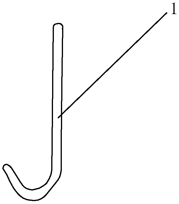
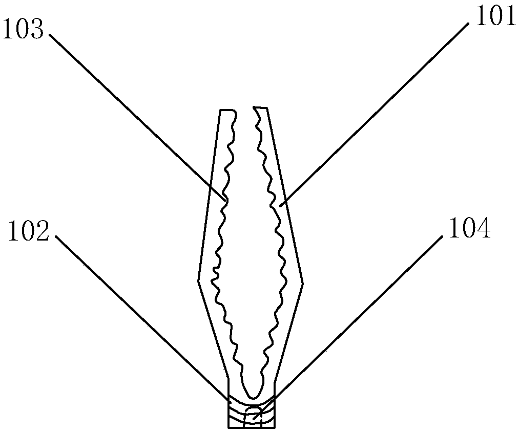
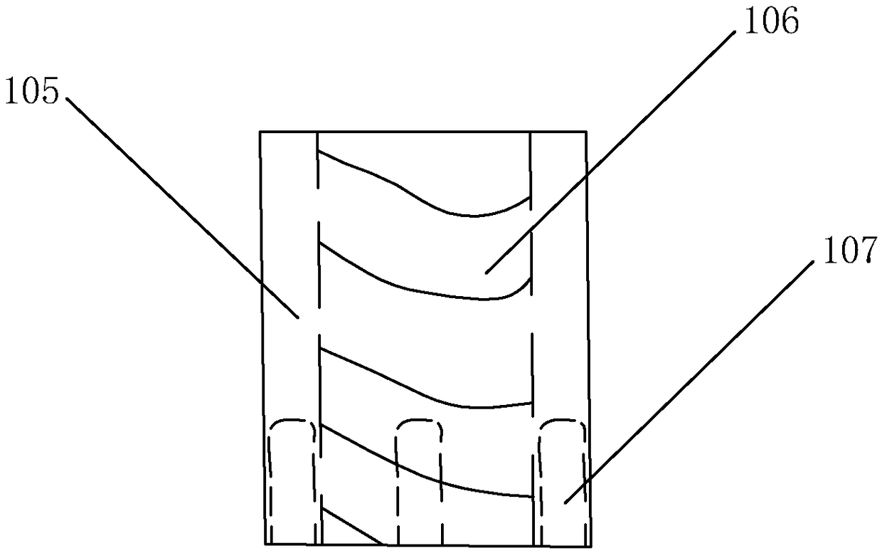
[0062] Figure 2 to Figure 5 It is a schematic structural diagram of a valve clamping device provided by Embodiment 1 of the present invention.

[0063] The clamping parts in the first embodiment are as figure 2 The clamping part is a set of clamps composed of two clamping arms 101 and a connecting part 102, which clamps the object in it by the interaction force generated by the two clamping arms 101 close to each other and squeeze. The single clamping arm 101 is V-shaped, and the V-shaped included angle is 140-165 degrees. The two clamping arms 101 are arranged symmetrically on both sides on the connecting member 102. When the two clamping arms 101 are not clamped, the plane between the two clamping arms 101 is basically a rhombus. After the two clamping arms 101 are close to each other and completely clamped, the outer shape of the two clamping arms 101 is cylindrical. The working surfaces of the two clamping arms 101 have a plurality of protrusions 103, the protrusions 103 a...

Embodiment 2

[0069] Figure 6 to Figure 9 It is a schematic structural diagram of the valve clamping device provided in the second embodiment of the present invention.

[0070] The clamping part in the second embodiment is such as Image 6 The clamping part is a set of clamps composed of two clamping arms 201 and a connecting part 202, which clamps objects in it through the interaction force generated by the two clamping arms 201 close to each other and squeeze. The single clamping arm 201 is V-shaped, and the V-shaped included angle is 140-165 degrees. The two clamping arms 201 are arranged symmetrically on both sides on the connecting member 202. When the two clamping arms 201 are not clamped, the plane between the two clamping arms 201 is basically a rhombus. After the two clamping arms 201 are close to each other and completely clamped, the outer shape of the two clamping arms 201 is a square column. The working surfaces of the two clamping arms 201 have a number of protrusions 203, the ...

Embodiment 3

[0076] Figure 10 to Figure 13 It is a schematic structural diagram of the valve clamping device provided in the third embodiment of the present invention.

[0077] The clamping parts in the third embodiment are as Picture 10 The clamping part is a set of clamps composed of two clamping arms 301 and a connecting part 302, which clamps the object in it by the interaction force generated by the two clamping arms 301 close together and squeeze. The single clamping arm 301 is V-shaped, and the V-shaped included angle is 140-165 degrees. The two clamping arms 301 are arranged symmetrically on both sides of the connecting member 302. When the two clamping arms 301 are not clamped, the plane between the two clamping arms 301 is basically a rhombus. After the two clamping arms 301 are close to each other and completely clamped, the outer shape of the two clamping arms 301 is a square column with a rhombus in longitudinal section. The working surfaces of the two clamping arms 301 have ...


PUM


Abstract

The invention discloses a valve clamping device for treating valvular heart diseases. The valve clamping device comprises a valve leaflet hook for lifting and fixing a valve leaflet, a clamping part for clamping an object in the clamping part through the interaction force produced by closing up and extrusion, a locking device arranged outside the clamping part and capable of making the clamping part tight in clamping and not displace, and a conveying device for conveying parts to an operation position in a minimally invasive way. The valve clamping device is applied to a lesion valve leaflet,normal chordae tendineae on two sides of the lesion part are close to each other by closing up free edges of the lesion valve leaflet, and accordingly the normal closing-up level of the valve leafletis rehabilitated. The valve clamping device has the advantages of being simple in structure, capable of achieving minimally invasive implantation, easy to operate and good in clamping effect and having clamping parts detachable or adjustable, can be applied to treatment of mitral regurgitation and tricuspid regurgitation and can be also used for other minimally invasive surgeries of several lamellar structures needing clamping.

Description

Technical field [0001] The invention relates to the field of medical instruments, specifically a surgical instrument, and more specifically a valve clamping device. Background technique [0002] Heart valve disease is a common heart disease. Mitral valve regurgitation, tricuspid valve regurgitation, and aortic valve regurgitation are the most common valvular heart diseases, and their incidence has been increasing significantly in recent years. The etiology can be divided into rheumatism, degenerative changes, congenital malformations, avascular necrosis, infection or trauma, etc., which affect the normal flow of blood, resulting in abnormal heart function, and eventually heart failure. With the aging of the population, senile valvular disease and valvular disease caused by coronary heart disease and myocardial infarction are becoming more and more common. [0003] Clinical trials have shown that drug treatment can only improve the symptoms of patients with valvular heart disease,...

Claims


Application Information

Patent Timeline
IPC IPC(8): A61B17/29
CPCA61B17/29A61B2017/2808A61B2017/2943A61B2576/023
Inventor 潘世伟汪胜胡盛寿
Owner 潘世伟
Why Eureka
Try Eureka