Multifunctional bionic mechanical pincer with autonomously-distributed power

A bionic machinery and multi-functional technology, applied in the field of bionic robots, can solve the problems of long charging time, single movement mode, wear and tear of connecting cables, etc., to improve the reliability of the whole machine, facilitate installation and disassembly, and reduce wear and tear failures.

Pending Publication Date: 2018-10-12
长沙紫宸科技开发有限公司
View PDF10 Cites 3 Cited by
  • Summary
  • Abstract
  • Description
  • Claims
  • Application Information

AI Technical Summary

Problems solved by technology

[0006] In the 12th issue of "Mechanics and Electronics" in 2009, a paper titled "Design and Realization of Bionic Crab Robot" was published. The bionic crab robot reported in this article has 2 claws, and each claw has 3 joints. Driven by 3 servo motors, it can realize functions such as picking up and transporting; however, this type of bionic pliers has the following defects: First, it only has the functions of bionic pliers for gripping, and has not realized the full sense of pliers and multiple defenses. The function is bionic; the second is that this kind of bionic pliers has no power of its own, and the power is concentrated on the main frame of the robot, which needs to be transmitted to the bionic pliers through cables, and it is easy to be paralyzed by the wear and tear of the connecting cables due to frequent movements; the third is its integral centralized The power supply has the problems of long charging time and low charging efficiency; fourth, this type of bionic pliers is connected to the power on the main frame, and installation and maintenance are mostly inconvenient
[0007] CN201610277479.2 discloses a multipurpose bionic crab robot, which includes a right clamp module and a left clamp module; the right clamp module is driven by a right clamp drive motor, a right clamp drive pinion, a right clamp drive gear, Right tong swivel arm, right tong primary drive hydraulic lever, right pivot pin, right tong primary drive arm, right tong secondary drive hydraulic lever, right tong secondary drive arm, right Side clamp third-stage drive hydraulic rod, right clamp third-stage drive arm, rotary cutting blade, auxiliary camera, flat-blade automatic screwdriver, cross automatic screwdriver, rotary cutting blade driving eccentric disk, rotary cutting blade driving disc motor, rotary The cutting blade drives the first connecting rod, the rotary cutting blade drives the second connecting rod, and the rotary cutting knife teeth; the left clamp module adopts a similar structure to realize the function of stretching the saw blade; the patent uses mechanical and hydraulic methods to realize the sawing of the bionic pincers. It has the characteristics of large clamping force and strong sawing ability, but it has the following defects: First, the power source is concentrated on the main frame of the bionic machine, and the hydraulic power system on the main frame of the robot needs to provide the joints of the claws. Hydraulic power is easily paralyzed due to wear and tear caused by frequent movement of connecting cables or hydraulic pipes; second, its integrated centralized power supply is arranged on the main body of the bionic robot, which has the problems of long charging time and low charging efficiency; third, the use of linear The joint motion of the oil cylinder and the driver present a nonlinear relationship, which leads to a complex control system; fourth, the bionic pliers and the connecting cables or / and hydraulic pipes arranged in it must be directly connected to the main frame of the robot, which is extremely inconvenient for disassembly and maintenance
[0008] CN201410581468.4 discloses a bionic crab robot, wherein the claw system includes a rack, and a claw main body is respectively installed at the symmetrical positions on the left and right sides of the rack, and each claw main body is composed of a fixed frame, a motor frame, swing steering gear, two connecting cards, tray, grabbing steering gear, two key-shaped gear rods, two claw rods and two connecting rods. This patent uses the mechanical method of the connecting rod mechanism to realize the bionic claw The clamping function has the following problems: First, the power source is concentrated on the main frame of the bionic machine, and a multi-part mechanical structure is used to transmit power, which is complicated in structure and poor in reliability; second, the movement mode is single, with few degrees of freedom, and only the clamping function is realized , the ability to adapt to complex working conditions is poor; the third is that its integrated centralized power supply is arranged on the main body of the bionic robot, which has the problems of long charging time and low charging efficiency; fourth, it is inconvenient to install and maintain
There are no research and practical reports on bionic claws with self-distributed power, which can be clamped, sawed, clamped, etc.

Method used


Image

  • Multifunctional bionic mechanical pincer with autonomously-distributed power
  • Multifunctional bionic mechanical pincer with autonomously-distributed power
  • Multifunctional bionic mechanical pincer with autonomously-distributed power

Examples


Embodiment 1

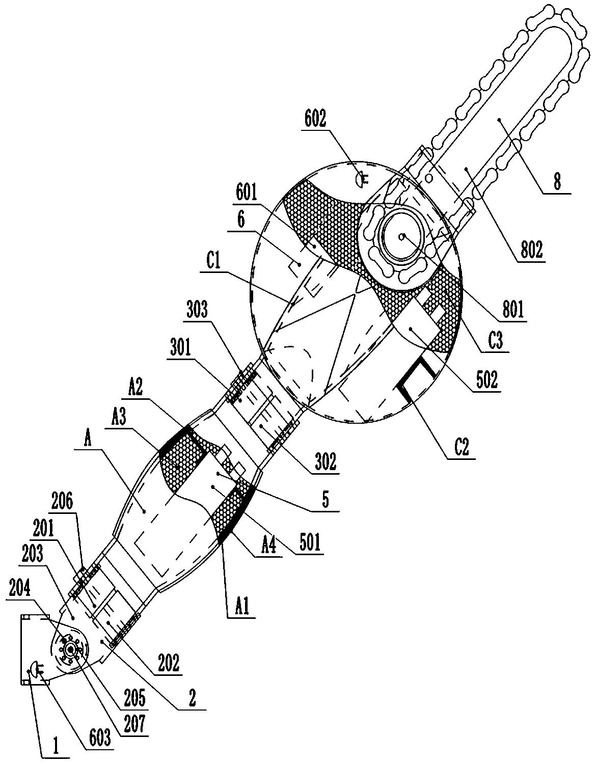
[0033] refer to figure 1 , figure 2 In this embodiment, the multifunctional bionic mechanical pincers with autonomously distributed power mainly include a connecting frame 1, a three-dimensional joint 2, a pincer joint A, a two-dimensional joint I3, a pincer shield joint C, a power device 5, an electric control device 6, a chain Saw 8; the three-dimensional joint 2 is fixed on the connecting frame 1 and connected with the claw joint A, the claw joint A is connected with the claw-shield joint C through the two-dimensional joint I3, the chain saw 8 is fixed on the claw-shield joint C, and the power device 5 mainly includes The battery pack I501 and the battery pack II502 are respectively fixed in the cavities of the claw joint A and the claw-shield joint C, and the electric control device 6 is fixed in the cavity of the claw-shield joint C, and the electric control device 6 is respectively connected with the power device 5 and the three-dimensional joint 2 , Two-dimensional jo...

Embodiment 2

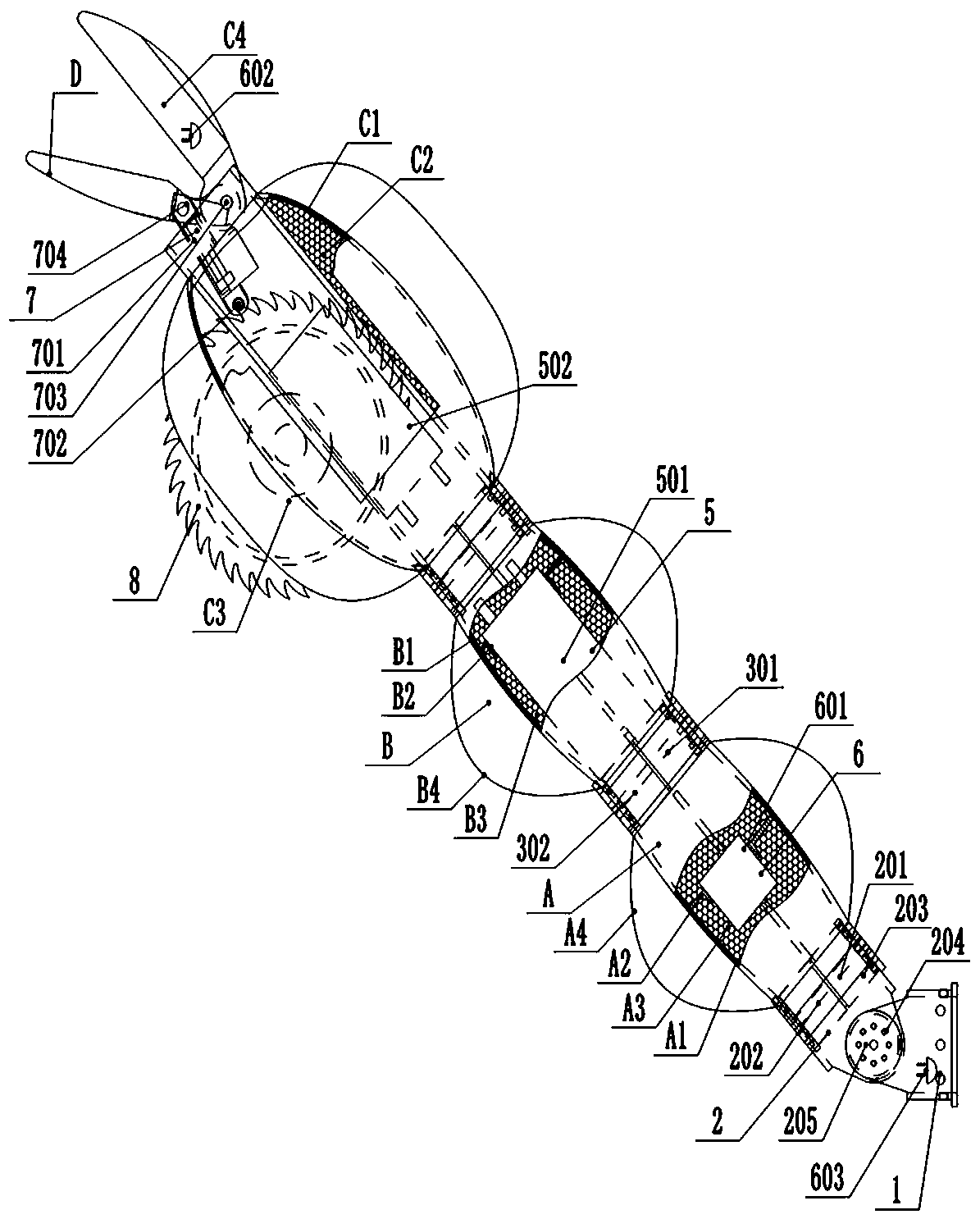
[0040] refer to image 3 , Figure 4 In this embodiment, the multifunctional bionic mechanical pliers with autonomously distributed power includes a connecting frame 1, a three-dimensional joint 2, a claw joint A, a two-dimensional joint I3, a claw joint B, a two-dimensional joint II4, a claw-shield joint C, and a forceps motion Mechanism 7, clamp D, power device 5, electric control device 6, circular saw 8; three-dimensional joint 2 is fixed on the connecting frame 1 and connected with claw A, and claw A is connected with claw B through two-dimensional joint I3, Claw segment B is connected to the claw segment C through the two-dimensional joint II4, and the claw segment C is connected to the clamp segment D through the clamp mechanism 7. The power unit 5 mainly includes a battery pack I501 and a battery pack II502, which are respectively fixed on the claw segment B and the clamp segment D. In the cavity of the chelicer-shield segment C, the electric control device 6 is fixed...

Embodiment 3

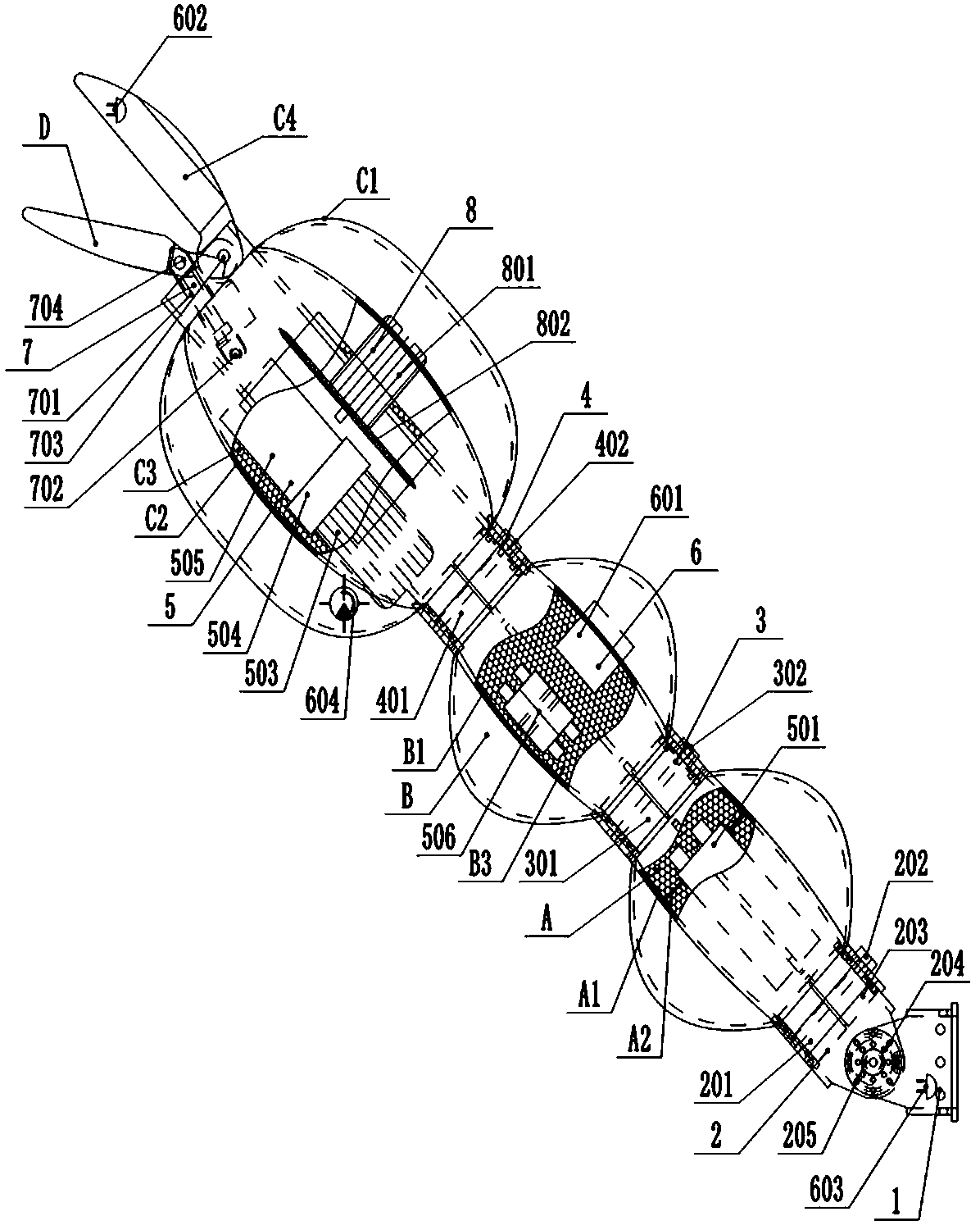
[0047] refer to Figure 5 , Figure 6 , in this embodiment, the difference between the multifunctional bionic mechanical pincers with autonomously distributed power and that of Embodiment 2 is only that:

[0048] The power device is a hydraulic power system, and the battery pack has only one battery pack I501, which also includes a drive motor 503, a hydraulic pump 504, a miniature oil tank 505, and a hydraulic solenoid valve group 506; the drive motor 503, hydraulic pump 504, and miniature oil tank 505 are connected in sequence Fixed in the cavity of claw-shield section C, hydraulic solenoid valve group 506 is fixed in the cavity of claw section B, and connected with hydraulic pump 504 through hydraulic pipelines; battery pack I 501 is fixed in the cavity of claw section A, and It is electrically connected with the drive motor 503; the electric control device 6 includes a controller 601, a charging port 602, an electrical plug-in 603, and a pressure sensor 604; the controlle...


PUM


Abstract

The invention relates to a multifunctional bionic mechanical pincer with autonomously-distributed power. The multifunctional bionic mechanical pincer comprises a pincer joint, a pincer shield joint and joints, and is further provided with a connecting frame, a power device, a saw and an electric control device; and the connecting frame, the pincer joint and the pincer shield joint are connected insequence through the joints, the power device is fixed into a cavity of the pincer joint or/and the pincer shield joint, the electric control device is fixed into the connecting frame or/and the cavity of the pincer joint or/and the pincer shield joint and is electrically connected with the power device and the joints, and the saw is fixed to the pincer shield joint. By means of the multifunctional bionic mechanical pincer, fixed connection and communication of the multifunctional bionic mechanical gripper and a bionic robot body can be achieved only through the connecting frame and an electric insertion piece, the structure is simple, and installation and detachment are facilitated; the working reliability is high, the charging efficiency is high, and dependency on the external energy resource is small; and the multifunctional bionic mechanical pincer is multiple in function and facilitates use of the bionic pincer in multiple aspects including earthquake rescue, security protection,military science investigation, outdoor expedition and the like.

Description

technical field [0001] The invention relates to the technical field of bionic robots, in particular to a multifunctional bionic mechanical pincer with autonomously distributed power. Background technique [0002] The research and development of bionic intelligent machinery is a hot topic that modern society pays more and more attention to. [0003] Inspired by the structure or structure of organisms with unique characteristics evolved by natural organisms, biomimicry researchers often imitate the structure of organisms to develop practical intelligent machines or robots. [0004] The scorpion's pincers have multiple degrees of freedom, good flexibility, and a shield-shaped defense structure, which has obvious advantages in daily detection, feeding, attack, and defense; Activities, such as earthquake rescue, security protection, underwater construction, military investigation, field exploration and other fields, have strong bionic significance. [0005] At present, there ar...

Claims


Application Information

Patent Timeline
Patent Type & Authority Applications(China)
IPC IPC(8): B25J9/00B25J17/00B25J17/02B25J9/16B25J19/00B23D57/02
CPCB23D57/02B25J9/00B25J9/0009B25J9/16B25J17/00B25J17/02B25J19/00
Inventor 尹小林韩建英
Owner 长沙紫宸科技开发有限公司
Why Eureka
Try Eureka