Injection mould core cooling device

A technology of cooling device and injection mold, which is applied in the field of molds, can solve the problems of affecting the flow of cooling water, inconvenient disassembly and assembly, and difficult processing, so as to shorten the injection molding cycle, facilitate processing and disassembly, and improve product quality.

Pending Publication Date: 2018-10-12
SUZHOU VOCATIONAL UNIV
View PDF1 Cites 1 Cited by
  • Summary
  • Abstract
  • Description
  • Claims
  • Application Information

AI Technical Summary

Problems solved by technology

[0003] The structure of the injection mold is generally composed of six parts: the pouring system, the guiding system, the molding system, the supporting system, the ejection system and the temperature control system; the principle of the molding system is to inject the molten resin with higher temperature into the lower temperature through high pressure injection. In the mold, the required product is obtained after cooling and solidification; therefore, product cooling is an important link in the molding process, and its cooling time accounts for about 50% to 60% of the molding cycle. In order to improve molding efficiency, it is usually used to shorten the cooling time. method to shorten the molding cycle, while the cooling rate and cooling uniformity also play an important role in the quality (such as surface finish, residual stress, thermal bending, etc.) and cost of plastic products; a die-casting mold is disclosed in the prior art 201420751995.0 Although the water inlet and outlet units can be rotated 360° in the same direction or in different directions at the same time, it is convenient for flexible installation, but there are the following problems: 1. Because the first point of the water transfer ring and the second point of the water transfer ring The position of the water transporter is fixed by the fixed block of the water transporter and the nut of the point water transporter, which leads to a high position accuracy requirement of the first point water transport ring and the second point water transport ring and the water inlet and outlet on the water inlet and outlet channel unit , otherwise it will not only affect the flow of cooling water, but also easily send and leak, making processing difficult and costly; 2. Since the water inlet and outlet units can rotate in the same direction or in different directions at the same time, the overall structure is complex and bulky, making it inconvenient to disassemble

Method used


Image

  • Injection mould core cooling device
  • Injection mould core cooling device
  • Injection mould core cooling device

Examples


Embodiment Construction

[0020] The present invention will be further described in detail below in conjunction with the accompanying drawings and specific embodiments.

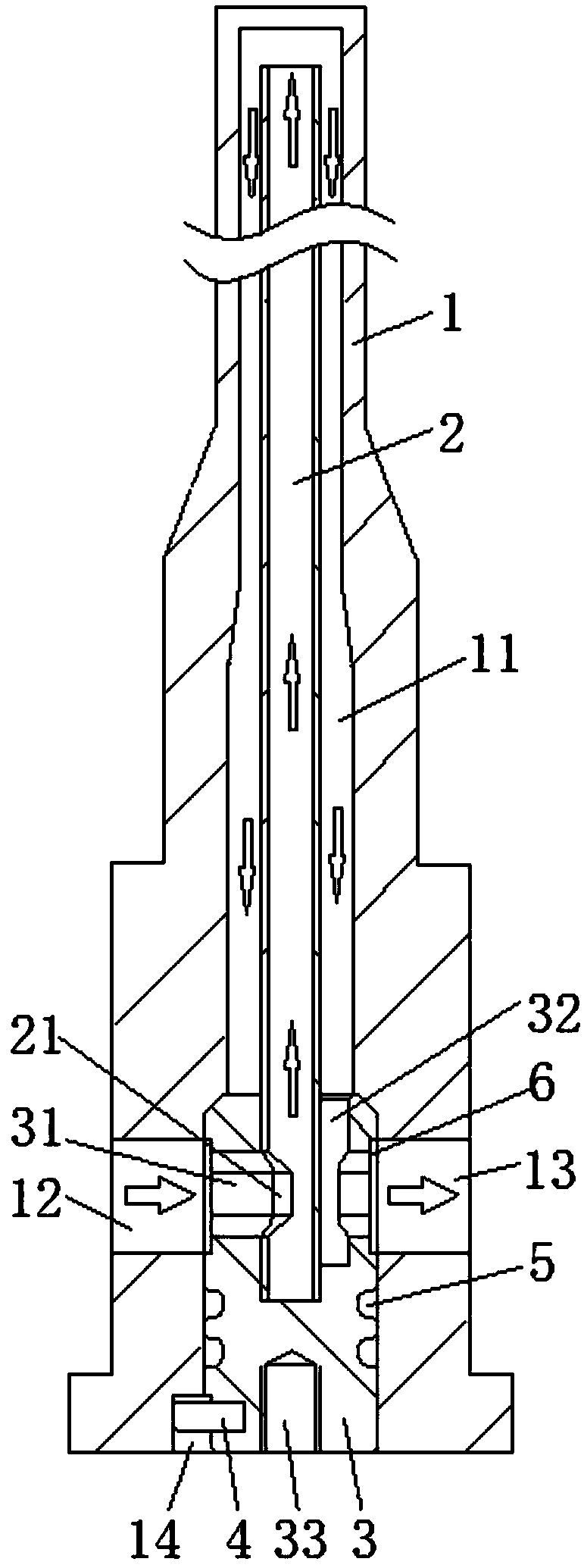
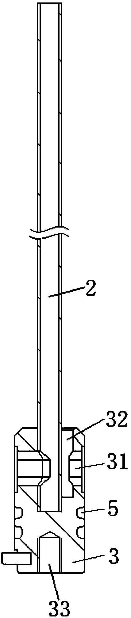
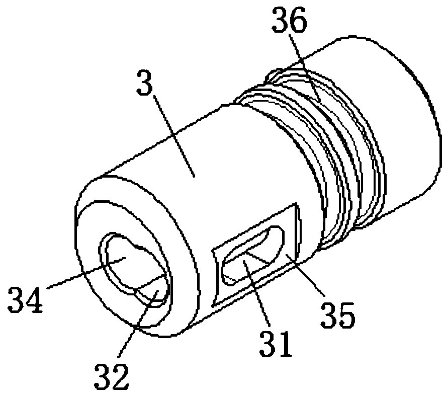
[0021] attached Figure 1-5 The injection mold core cooling device according to the present invention includes a slender core 1, a stepped blind hole 11 arranged at the bottom of the core 1 and placed coaxially with the core 1, and an opening set in the stepped blind hole 11. The drainage column 3 located at the end and through the shoulder of the hole, the through hole 31 arranged on the surface of the drainage column 3 and perpendicular to the drainage column 3, the water inlet 12 and the The water outlet 13, the water inlet hole 34 and the water outlet hole 32 which are respectively arranged at the inner end of the drainage column 3 and perpendicularly intersect with the through hole 31, the water inlet pipe 2 which is arranged in the stepped blind hole 11 and one end is placed in the water inlet hole 34, The positioning chute 14 ...


PUM


Abstract

The invention relates to an injection mould core cooling device. The injection mould core cooling device comprises a slender-type core, a ladder blind hole, a drainage column, a through hole, a waterinlet, a water outlet, a water inflow hole, a water outflow hole, a water inflow pipe, a locating pin, a seal ring and a disassembly and assembly threaded hole; the ladder blind hole coaxially placedis formed in the bottom of the core; the drainage column is arranged at the opened end of the ladder blind hole and is located through a hole shoulder; the through hole vertically placed is formed inthe surface of the drainage column; the water inlet and the water outlet are correspondingly formed in the surface of the core and are correspondingly placed at the two ends of the through hole; the water inflow hole and the water outflow hole are correspondingly formed in the inner end of the drainage column and are intersected with the through hole; the water inflow pipe is arranged in the ladder blind hole; one end of the water inflow pipe is arranged in the water inflow hole; one end of the locating pin is arranged on the drainage column; the other end of the locating pin is arranged in the core; the seal ring is arranged on the surface of the drainage column and is located between the through hole and the locating pin; the disassembly and assembly threaded hole is formed in the outerend of the drainage column; and a gap which corresponds to the cross section of the through hole and is placed towards the direction of the water inlet is formed in the water inflow pipe. The injection moulding cycle can be shortened, the quality of products is improved, and the injection mould core cooling device is simple in structure, small in size, convenient to machine and convenient in disassembly and assembly.

Description

technical field [0001] The invention relates to the field of molds, in particular to an injection mold core cooling device. Background technique [0002] Mold is an important process equipment in industrial production. With the development of automobile, home appliance, aviation, instrumentation and daily necessities industry, the demand for plastic molding products is increasing; therefore, the level of mold design and the strength of mold manufacturing ability Weakness and the quality of the mold will directly affect the quality and efficiency of plastic products. [0003] The structure of the injection mold is generally composed of six parts: the pouring system, the guiding system, the molding system, the supporting system, the ejection system and the temperature control system; the principle of the molding system is to inject the molten resin with higher temperature into the lower temperature through high pressure injection. In the mold, the required product is obtained...

Claims


Application Information

Patent Timeline
Patent Type & Authority Applications(China)
IPC IPC(8): B29C45/73
CPCB29C45/7312
Inventor 李耀辉
Owner SUZHOU VOCATIONAL UNIV
Why Eureka
Try Eureka