Eureka AIR delivers breakthrough ideas for toughest innovation challenges, trusted by R&D personnel around the world.

Method and device for obtaining high-voltage electricity surface unipolar discharging trace

A discharge trace and surface discharge technology, applied in special decorative structures, decorative art, etc., can solve the problems of short circuit on the surface of products, different discharge trace directions and distribution patterns, and affect the directionality and continuity of discharge trace patterns, etc., to achieve uniform development , Guaranteed pattern continuity and simple structure

Active Publication Date: 2018-10-12
BEIJING UNIV OF TECH
View PDF2 Cites 2 Cited by
  • Summary
  • Abstract
  • Description
  • Claims
  • Application Information

AI Technical Summary

Problems solved by technology

Third, when the positive and negative electrodes develop discharge traces at the same time, the direction and distribution pattern of the discharge traces extending from the two electrodes are different, thus affecting the directionality and continuity of the discharge trace pattern
Fourth, the carbonized discharge traces left by surface discharge are conductors, and the discharge traces are equivalent to extending the lead-out electrodes. If the positive and negative electrodes develop discharge traces at the same time, the discharge traces of the two electrodes tend to be connected at the shortest distance, resulting in a short circuit on the surface of the product, which is easy Leaving blank areas that are difficult to fill near the junctions of discharge traces
However, if it is not controlled in the actual implementation, regardless of the use of AC, pulse and DC, surface discharge may occur and develop at more than one electrode at the same time, limiting the application value of surface discharge traces in product surface modification methods

Method used


Image

  • Method and device for obtaining high-voltage electricity surface unipolar discharging trace
  • Method and device for obtaining high-voltage electricity surface unipolar discharging trace
  • Method and device for obtaining high-voltage electricity surface unipolar discharging trace

Examples


Embodiment 5

[0032] Example 5 provides a counter example to illustrate the effect of the peak voltage higher than 3kV between the positive and negative electrodes when there is no load. The self-excited push-pull boost power supply is used as a control device, and the power structure is a self-excited push-pull ZVS boost with frequency open loop control. The circuit has a working frequency range of 13-42kHz. After rectifying the output of the power supply into a pulsating direct current and connecting it to the positive and negative electrodes, the no-load peak voltage between the electrodes is 10kV. The peak power of the device is 200W, the rectifier circuit is the same as the rectifier circuit in the test device of the present invention, and the test device and the control device use the same electrode group to provide the conditions required for the control test.

[0033] In Examples 1 to 3, the surface discharge starts at the first power supply condition. After the discharge trace covers a...

Embodiment 1

[0036] In this example, conditions 1 to 3 illustrate the feasibility of unipolar discharge, and conditions 4 to 5 are used as a comparison to illustrate the significance of unipolar discharge; condition 6 illustrates the occurrence of another polarity discharge during unipolar surface discharge And development is inhibited or cannot happen. In 9M NiCl 2 Add 2.3wt.% SiO to the aqueous solution 2 , 4.2wt.% PEG-200 is used as the conductive agent used in this embodiment, and the metal ion charge concentration is 18M. The volume of the conductive agent applied to the test range of the modified article is 1.0ml.

Embodiment 1

[0037] Example 1 Condition 1. Using the test device 1, the electrode is loaded with a pulsating direct current of 35 kHz and a duty ratio of 0.3. During surface discharge, the peak voltage is 0.78kV and the power consumption is 25W.

[0038] Example 1 Condition 2. Using the test device 2, the electrode is loaded with a pulsating direct current of 18 kHz and a duty ratio of 0.4. During surface discharge, the peak voltage is 0.91kV and the power consumption is 55W.

[0039] Example 1 Condition 3. Using the test device 3, the electrode is loaded with a pulsating direct current of 120kHz and a duty ratio of 0.5. During the surface discharge process, the peak voltage is 0.98kV and the power consumption is 7.5W.

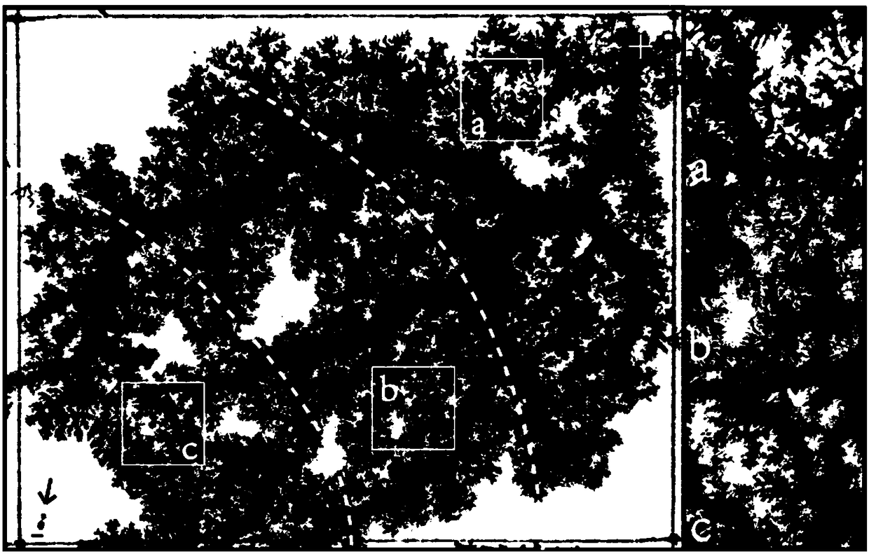
[0040] The implementation results of conditions 1 to 3 of Example 1 are as follows figure 2 . The oblique line in the figure is the dividing line for switching power supply conditions. The implementation results of conditions 1 to 3 are divided from right to left. There is...


PUM


Abstract

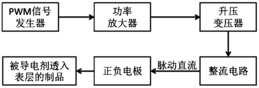
The invention provides a method and device for obtaining a high-voltage electricity surface unipolar discharging trace. Through cooperation of a conductive additive, the unipolar discharging trace canbe obtained on the surface of a product through pulse direct current. In the method and the device, a PWM signal generator generates a drive signal, a direct-current pulse voltage is obtained by stimulating a boosting transformer and a rectifying circuit through a power amplifier, the voltage is transmitted to a positive electrode and a negative electrode, the positive electrode and the negativeelectrode are then placed on the product where the conductive additive permeates the surface layer, surface discharging is conducted from an anode or a cathode, and the unipolar discharging trace is left on the surface layer of the product. The macroscopic pattern of the discharging trace has fractal features and can be used for artistic creation, fractal picture template manufacture and craft manufacture. Compared with a method and device for obtaining a discharging trace by applying the industry alternating-current high voltage on the surface of a wet material, the method has the beneficialeffects that unipolar control is achieved, operability is high and pattern continuity is ensured; and the device has the beneficial effects that the device is easy to obtain and the structure is simple.

Description

Technical field [0001] The invention relates to a method and a device for obtaining discharge traces on the surface of a product, in particular to a method and a device for obtaining unipolar discharge traces on a high-voltage electrical surface. Background technique [0002] Surface discharge is a discharge phenomenon along the interface of different aggregated dielectrics. The invention applies a high voltage after penetrating the surface of the product with a conductive agent to cause the product to produce a strip-shaped surface discharge. The surface discharge develops in the form of a discharge belt advancing on the surface of the product, leaving a discharge trace in the form of carbonization of the material surface, thereby The macroscopic pattern of the formed discharge trace has fractal characteristics, its details are highly random and the macroscopic direction is controllable. At the same time, the macro pattern of discharge traces has different distribution patterns...

Claims


Application Information

Patent Timeline
Patent Type & Authority Applications(China)
IPC IPC(8): B44C5/00H02M9/00
Inventor 李钒金天
Owner BEIJING UNIV OF TECH
Why Eureka
Eureka Blog
Learn More