Resistance wire liquid heater for heat management of new energy automobiles

A technology for liquid heaters and new energy vehicles, which is applied in heating/cooling equipment, vehicle parts, air handling equipment, etc. It can solve problems such as inability to guarantee high-precision flatness, small contact surface, ignition and arcing, and vehicle loss. Achieve the effect of good intelligent utilization rate and rapid temperature rise

Active Publication Date: 2018-10-12
安徽省宁国市天成电气有限公司
View PDF6 Cites 2 Cited by
  • Summary
  • Abstract
  • Description
  • Claims
  • Application Information

AI Technical Summary

Problems solved by technology

[0004] The above-mentioned patent is only a scheme form of the PTC heating tube body, but the key points for application in new energy vehicles are safety, efficiency, and intelligence, which require multiple safety protection designs to form intelligent information interaction with the vehicle. The temperature requirements of the actual vehicle and the battery information signal make the most efficient and safe heating output; therefore, this patent has no control method, no efficient assembly design, no safety protection measures, etc.; in addition, the PTC heating sheet and the There are certain disadvantages in the technology of sticking the electrode plate to the electrode plate. The reason is that the original wave-shaped electrode plate cannot guarantee high-precision flatness after being drawn and deformed, so that it cannot be in effective surface contact with the PTC heating sheet, and the electrode will expand after thermal expansion and contraction after aging. It is prone to the problem of small ignition and arcing on the contact surface, which will cause heavy losses to the car

Method used


Image

  • Resistance wire liquid heater for heat management of new energy automobiles
  • Resistance wire liquid heater for heat management of new energy automobiles
  • Resistance wire liquid heater for heat management of new energy automobiles

Examples


Embodiment Construction

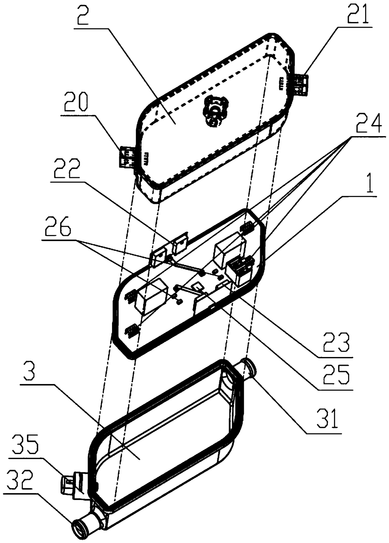
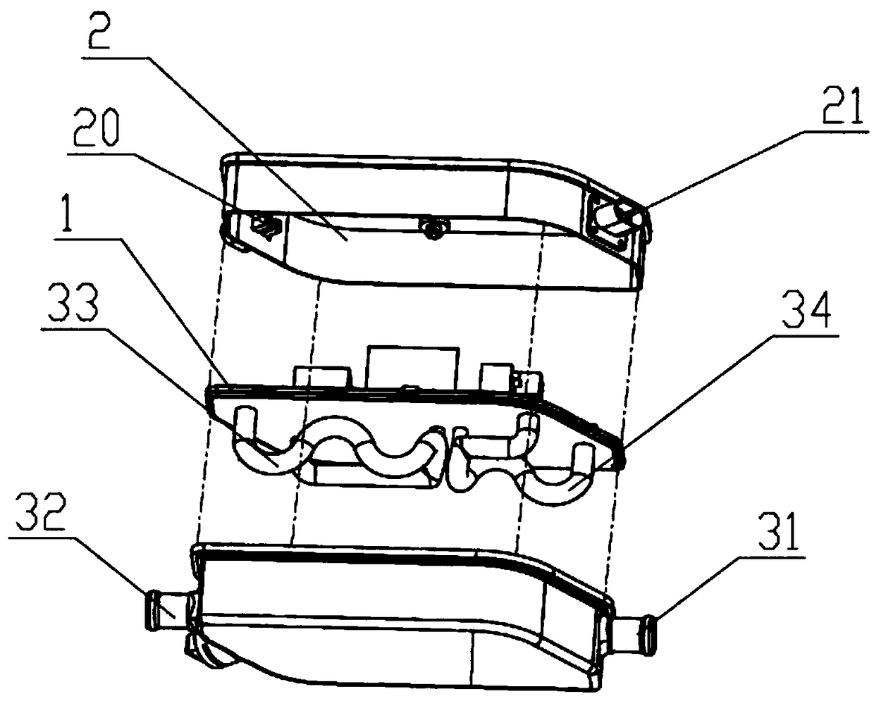
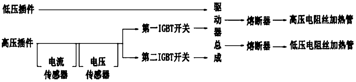
[0022] Such as Figure 1-3 as shown, figure 1 It is an explosion schematic diagram of a resistance wire liquid heater for thermal management of a new energy vehicle proposed by the present invention, figure 2 It is an explosion schematic diagram of a resistance wire liquid heater for thermal management of a new energy vehicle proposed by the present invention, image 3 It is a schematic diagram of the current flow of a resistance wire liquid heater for thermal management of a new energy vehicle proposed by the present invention.

[0023] refer to Figure 1-3, a resistance wire liquid heater for thermal management of new energy vehicles proposed by the present invention is mainly used in battery thermal management systems and air-conditioning thermal management systems, and includes a heater housing, which is provided with a separator 1 to heat The interior of the housing is separated to form a control chamber 2 and a heat exchange chamber 3; the control chamber 2 is provid...


PUM


Abstract

The invention discloses a resistance wire liquid heater for heat management of new energy automobiles. The inner portion of a heater shell is divided into a control chamber and a heat exchange chamber. A low-voltage inserting piece in the control chamber is connected with a driver assembly; a high-voltage inserting piece is connected with a first IGBT switch and a second IGBT switch, and the firstIGBT switch and the second IGBT switch are connected with the driver assembly. A high-voltage resistance wire heating pipe and a low-voltage resistance wire heating pipe are arranged in the heat exchange chamber, wherein the high-voltage resistance wire heating pipe and the low-voltage resistance wire heating pipe are connected with the driver assembly. Under a first working condition, a voltagesensor controls the working voltage to be transmitted to the high-voltage resistance wire heating pipe through the first IGBT switch and the driver assembly, and the high-voltage resistance wire heating pipe starts heating. Under a second working condition, the voltage sensor controls the working voltage to be transmitted to the low-voltage resistance wire heating pipe through the second IGBT switch and the driver assembly, and the low-voltage resistance wire heating pipe starts heating to meet the heating demand of the power battery at low voltage, and the high-voltage demand under normal full power condition so as to achieve the best intelligent utilization ratio.

Description

technical field [0001] The invention relates to the technical field of liquid heaters for new energy vehicles, in particular to a resistance wire liquid heater for thermal management of new energy vehicles. Background technique [0002] With the rapid development of electric vehicles in recent years, safety, efficiency, battery life, and intelligence are particularly important in the popularization of electric vehicles. Car companies have designed battery thermal management systems for power batteries, and air-conditioning thermal management systems for heating and defrosting. The liquid heater is an important part of the battery thermal management system and the air conditioner thermal management system. The current existing liquid heater technologies are as follows: [0003] A PTC electric heating tube and an electric vehicle water heating heater are characterized in that it includes a heating element, an electrode plate, a solid insulating layer, a spacer and a metal tube...

Claims


Application Information

Patent Timeline
IPC IPC(8): B60H1/22
CPCB60H1/2215B60H1/2218
Inventor 赵长彬郭晓康
Owner 安徽省宁国市天成电气有限公司
Why Eureka
Try Eureka