
Single wavelength multiline scanning system based on thermo-optic switches and silicon optical phased array

A technology of thermo-optic switch and optical phased array, applied in the field of multi-line scanning system, can solve the problems that are not suitable for the actual scene of phased array lidar, large frequency band resources, etc., and achieve large-scale integration, small size, and easy production Effect

Inactive Publication Date: 2018-10-12
ZHEJIANG UNIV
View PDF4 Cites 29 Cited by
  • Summary
  • Abstract
  • Description
  • Claims
  • Application Information

AI Technical Summary

Problems solved by technology

However, the phased array principle shows that if the array element spacing is greater than half the wavelength, grating lobes will appear, and sector gratings are prone to many grating lobes, which is not suitable for the actual scene of phased array lidar
Strip waveguide gratings can greatly reduce the distance between array elements, but the strip waveguide gratings arranged in one dimension can only realize the phase control beam deflection in one dimension, and the other dimension is usually to change the wavelength to control the radiation elevation angle.
However, the optical phased array beam hemispherical deflection of one-dimensional grating array needs to occupy a lot of frequency band resources
So far, there is no scheme to achieve hemispherical beam deflection in azimuth and elevation at the same time only through a single-wavelength light source

Method used


Image

  • Single wavelength multiline scanning system based on thermo-optic switches and silicon optical phased array
  • Single wavelength multiline scanning system based on thermo-optic switches and silicon optical phased array
  • Single wavelength multiline scanning system based on thermo-optic switches and silicon optical phased array

Examples


Embodiment Construction

[0028] The present invention will be further described below in conjunction with the accompanying drawings and embodiments.

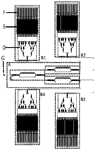
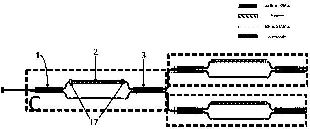
[0029] Such as figure 1 As shown, the present invention includes a channel selection module A and 4 optical phased array unit modules B1, B2, B3 and B4 with the same structure; wherein: the channel selection module A includes 3 MZ-MMI thermo-optic switches C with the same structure ( It can be expanded to N level), the input of the first MZ-MMI thermo-optic switch C is coupled with the CW laser source G through the grating, the input of the first MZ-MMI thermo-optic switch C is through its own two interference arms and 2×2MMI 3 There are 2 outputs at the end, and the 2 outputs are respectively connected to the input of the second MZ-MMI thermo-optic switch C and the input of the third MZ-MMI thermo-optic switch C, and the input of the second MZ-MMI thermo-optic switch C passes through itself There are 2 outputs behind the two interference arms and 2×2M...


PUM


Abstract

The invention discloses a single wavelength multiline scanning system based on thermo-optic switches and a silicon optical phased array. MZ-MMI thermo-optic switches form a channel selection module through cascading, and the output end is connected with the optical phased array unit modules of different grating period coupled grating arrays. Each optical phased array unit module comprises a beam splitter module formed by the cascaded 1x2MMI, a waveguide connection module, a thermo-optic phase shifter array and a coupled grating array. The cascaded thermo-optic switches are applied to select and switch different optical phased array modules, different grating periods of coupled grating arrays are applied for radiation in the aspect of device, beam elevation control is realized in the aspectof effect and the frequency band resource can be greatly saved. Besides, the silicon-based optoelectronic device has the characteristics of being small in size and compatible with the CMOS technologyso that manufacturing is easy and large-scale integration can be realized. The size of the whole set of system is far less than that of other radar scanning systems, and full coverage scanning of thebeams on the hemispherical surface can be realized by only using single wavelength.

Description

technical field [0001] The invention relates to a multi-line scanning system, in particular to a single-wavelength multi-line scanning system based on a thermo-optical switch and a silicon photophased array. Background technique [0002] The concept of phased array radar originated in the 1950s and 1960s. Traditional electrical antennas have the characteristics of large volume, high requirements for feeding strength, wide beam, and slow mechanical rotation speed for deflection. In the field of radar monitoring and communication, traditional antennas are gradually unable to adapt to more demanding application scenarios. At this time, a new radar antenna technology-phased array antenna emerged. As the name implies, the phased array antenna uses multiple antenna elements capable of radiating electromagnetic wave energy, which are arranged in specific relative positions in space. By adjusting the phase shifter at the feed end, the phase difference between the elements is chang...

Claims


Application Information

Patent Timeline
IPC IPC(8): G02B27/44G02F1/01G02F1/29
CPCG02B27/44G02F1/0147G02F1/292
Inventor 忻勤杰余辉王健江晓清
Owner ZHEJIANG UNIV
Learn More