Electro-hydraulic mix-drive pipe bender
A technology of electro-hydraulic mixing and pipe bending machine, which is applied in the field of hydraulic drive, can solve the problems of high cost and complex structure, and achieve the effects of convenient operation, high control precision and simple structure
- Summary
- Abstract
- Description
- Claims
- Application Information
AI Technical Summary
Problems solved by technology
Method used
Image
Examples
Embodiment 1
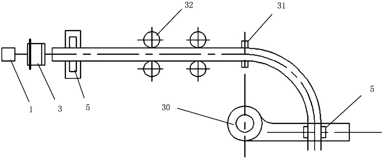
[0049] Such as figure 1 As shown, an electro-hydraulic hybrid driven pipe bender includes a pushing cylinder 3, a waist drum roller 32, an induction coil 31, a rocker arm 30, a clamping motor 5 and a second hydraulic drive circuit 2.
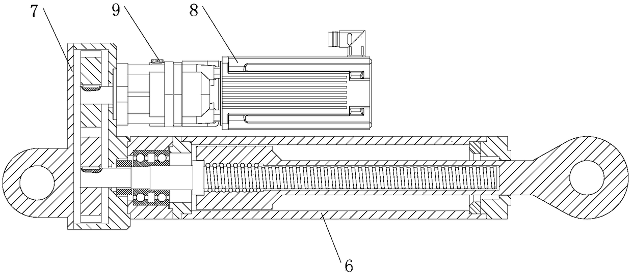
[0050] Such as figure 2 and 6 As shown, the pushing cylinder is an electro-hydraulic mechanical cylinder, and the electro-hydraulic mechanical cylinder includes: the first variable pump / motor 8, the first servo motor 9, the first transmission pair 7 and the first lead screw 6, the first servo The output end of the motor is connected in series with the input end of the first variable pump / motor, the output shaft of the first variable pump / motor is mechanically connected with the first transmission pair, and the first lead screw is mechanically connected with the first transmission pair.
[0051] Such as Figure 6 As shown, the second hydraulic drive circuit includes: power source 19, main hydraulic pump 18, first filter 17, oil tank 16, first...
Embodiment 2
[0054] Such as figure 1 As shown, an electro-hydraulic hybrid driven pipe bender includes a pushing cylinder 3, a waist drum roller 32, an induction coil 31, a rocker arm 30, a clamping motor 5 and a first hydraulic drive circuit 1.
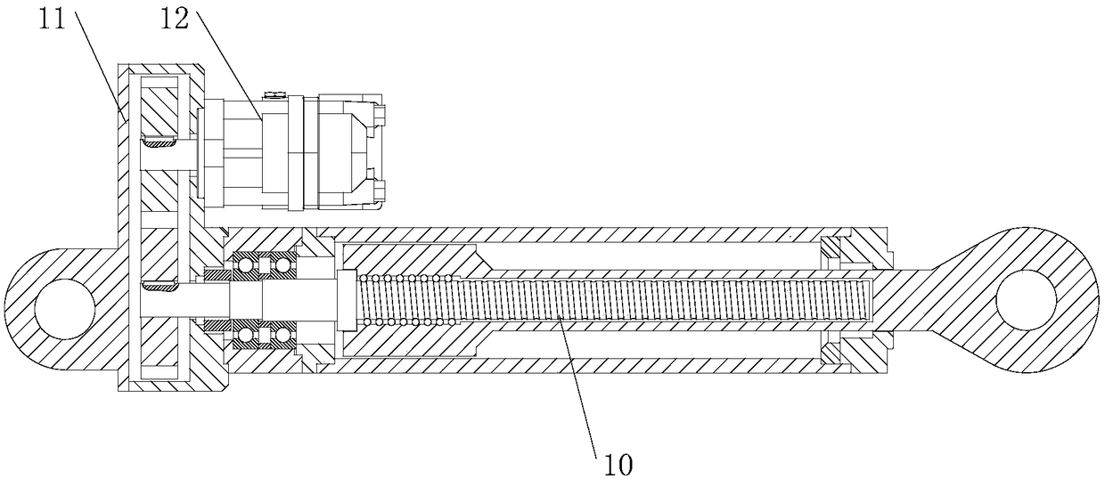
[0055] Such as image 3 and 7 As shown, the pushing cylinder is a hydraulic mechanical cylinder, and the hydraulic mechanical cylinder includes: the second variable pump / motor 12, the second transmission pair 11 and the second lead screw 10, the output end of the second variable pump / motor and the second The input end of the transmission pair II is connected in series, and the second lead screw and the second transmission pair are mechanically connected.
[0056] Such as Figure 7 As shown, the first hydraulic drive circuit includes: power source 19, main hydraulic pump 18, first filter 17, oil tank 16, first relief valve 20, first one-way valve 21, second relief valve 23. Pressure switch valve 22, II accumulator 25, III overflow valve 26, II...
PUM
 Abstract
Description
Claims
Application Information
 - R&D
- Intellectual Property
- Life Sciences
- Materials
- Tech Scout
- Unparalleled Data Quality
- Higher Quality Content
- 60% Fewer Hallucinations
Browse by: Latest US Patents, China's latest patents, Technical Efficacy Thesaurus, Application Domain, Technology Topic, Popular Technical Reports.
© 2025 PatSnap. All rights reserved.Legal|Privacy policy|Modern Slavery Act Transparency Statement|Sitemap|About US| Contact US: help@patsnap.com


