Deep-hole boring machine for machining roller shell of roller of cast rolling machine

A roll sleeve, casting and rolling mill technology, applied in metal processing machinery parts, metal processing equipment, parts of boring machines/drilling machines, etc. The effect of increased depth and efficiency, smaller overall equipment size, and increased drive torque

Pending Publication Date: 2018-10-16
洛阳广纬精工科技有限公司
View PDF0 Cites 3 Cited by
  • Summary
  • Abstract
  • Description
  • Claims
  • Application Information

AI Technical Summary

Problems solved by technology

[0003] Casting mill roll sleeves belong to thick leather tube parts. The ideal processing method for thick leather tube parts can be deep hole boring. Low efficiency of rolling mill roll sleeves
[0004] Traditional deep hole boring usually consists of a large spindle gearbox with a chuck, which holds a large workpiece for rotary motion, followed by a complex boring bar feeding gearbox with a single-head supported boring bar for feeding Movement; this structure has the following defects: 1. Since the large workpiece requires rotation, the power of the spindle must overcome the weight and centrifugal force of the large workpiece itself, so the gearbox torque is required to be large and the strength of the manufacturing material is high, and the corresponding movement is relatively complicated. The demand is also large; 2. The boring bar is supported by a single head. When the feeding depth of the boring bar is deepened, the boring bar droops due to its own weight, the speed is very low, and the feed rate is very small. When the feed rate exceeds half, in order to prevent the boring bar from drooping , it is necessary to pad hard wood near the boring head, so that not only the rotational friction becomes larger, but also consumes more power, and the feed rate of the cutting tool cannot be too large, and the processing efficiency is extremely low; 3. The workpiece and the boring bar are installed independently, although there are It is beneficial to the up and down of parts, but the overall volume of the equipment is large and heavy

Method used


Image

  • Deep-hole boring machine for machining roller shell of roller of cast rolling machine
  • Deep-hole boring machine for machining roller shell of roller of cast rolling machine
  • Deep-hole boring machine for machining roller shell of roller of cast rolling machine

Examples


Embodiment 1

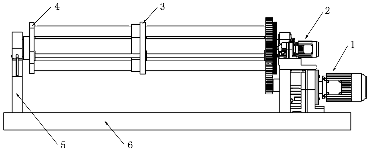
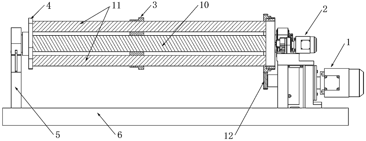
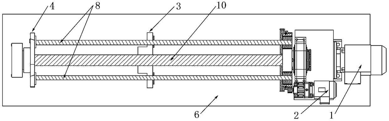
[0026] refer to Figure 1 to Figure 5 , a deep hole boring machine for processing roll sleeves of casting and rolling mills, comprising a base 6, a frame 5, a main boring bar 10, an auxiliary boring bar 11, a boring tool holder 3 and a feed screw 14; the frame 5 is fixedly arranged on base 6;

[0027] Both ends of the main boring bar 10 are rotatably supported by the frame 5, one end of the main boring bar 10 is fixedly connected with a support plate 4, and the other end of the main boring bar 10 is fixedly connected with a boring bar driving gear 13, and the supporting plate 4 and the boring bar driving gear 13 are both Located between the two support points of the main boring bar 10, there are two auxiliary boring bars 11 that are symmetrically and evenly distributed around the main boring bar 10 centered on the axis line of the main boring bar 10, and the two ends of the auxiliary boring bar 11 are respectively fixedly connected to the The supporting plate 4 and the boring...

Embodiment 2

[0034] refer to Figure 1 to Figure 5 , a deep-hole boring machine for processing roll sleeves of casting and rolling mills. Compared with Embodiment 1: the supporting part of the ring gear 7 is still rotated and arranged in the cylindrical accommodation space of the boring bar drive gear 13, but no bearings are used, and It is to directly use the steel ball 15 (such as Figure 5shown) to perform axial and radial positioning so that the two can only rotate relative to each other, that is, the inner wall of the cylindrical accommodation space of the boring bar driving gear 13 and the outer periphery of the supporting part of the ring gear 7 are correspondingly provided with annular grooves, and the steel balls 15 is arranged in the annular groove to realize the axial and radial positioning between the cylindrical accommodation space of the boring rod driving gear 13 and the support part of the ring gear 7 (that is, compared with Embodiment 1, the rod driving gear 13 cylinder T...

Embodiment 3

[0036] refer to Figure 1 to Figure 4 as well as Figure 6 , a deep hole boring machine for processing roll sleeves of casting and rolling mills. The difference from Embodiment 1 is that the ring gear 7 is not installed in the boring bar driving gear 13 for rotation, but adopts such as Figure 4 In the shown structure, the side of the ring gear 7 facing away from the boring bar driving gear 13 is provided with a boring bar driving gear hub, and the boring bar driving gear hub is rotatably arranged on the main boring bar 10 .

[0037] In the above embodiments, the rotary motion of the feed screw 14 is divided into the motion of following the main boring bar 10 (or the boring bar driving gear 13) around the axis of the main boring bar 10 and the rotation around the axis of the feed screw 14 itself. Among them, the power transmission direction of the revolution movement of the feed screw 14 is: boring bar motor 1 → boring bar motor output gear 12 → boring bar driving gear 13 and...


PUM


Abstract

The invention relates to the technical field of deep-hole boring machines, in particular to a deep-hole boring machine for machining a roller shell of a roller of a cast rolling machine. An independent variable frequency motor is adopted as a lead screw motor to drive feed lead screws, and in combination with a boring rod motor, stepless variable speed control over axial feeding of a boring cuttershaft is jointly achieved; and by the adoption of a gear ring simultaneously provided with inner teeth and outer teeth, synthesis motion of rotation of the feed lead screws around the axes of the feed lead screws and rotation of the feed lead screws around the axial line of a main boring rod is achieved. The technical problem of drooping of the boring rod is solved through two-end supporting. Thedeep-hole boring machine is simple in structure, relatively small in equipment total volume, low in power consumption and high in machining efficiency.

Description

technical field [0001] The invention relates to the technical field of deep hole boring machines, in particular to a deep hole boring machine for processing roll sleeves of casting and rolling mills. Background technique [0002] The roll of the casting-rolling machine is a key part of the casting-rolling machine. Because it needs to be rotated and cooled inside, it needs to be sealed well, so the precision of the inner hole is high. In addition, due to the erosion of the molten metal, the wear of the roll is also very large, so the consumption of the roll is also high. It is very fast, so how to improve the processing and repairing efficiency of the roll is the key to improving the efficiency of the casting and rolling mill. [0003] Casting mill roll sleeves belong to thick leather tube parts. The ideal processing method for thick leather tube parts can be deep hole boring. Rolling mill roll sleeves are less efficient. [0004] Traditional deep hole boring usually consis...

Claims


Application Information

Patent Timeline
Patent Type & Authority Applications(China)
IPC IPC(8): B23B41/02B23B47/00B23B47/20
CPCB23B41/02B23B47/00B23Q5/40B23Q5/402Y02P70/10
Inventor 陈建立李海欣李辉
Owner 洛阳广纬精工科技有限公司
Why Eureka
Try Eureka