
An edging machine with a manipulator for processing rearview mirror lenses

A lens processing and manipulator technology, applied in the field of mechanical equipment, can solve problems such as difficult to promote on a large scale, imprecise edging, complex structure, etc.

Active Publication Date: 2019-11-08
台州市星煜车辆部件有限公司
View PDF1 Cites 0 Cited by
  • Summary
  • Abstract
  • Description
  • Claims
  • Application Information

AI Technical Summary

Problems solved by technology

The above lens feeding and edging, and the transportation of the lens after grinding are mainly completed by the conveyor belt, assisted by the manipulator, the structure is relatively complicated, and the conveyor belt is not positioned when transporting the lens, the manipulator is mechanically operated, and the lens is easy. Misalignment on the conveyor belt resulting in inaccurate lens edging
To sum up, the structure of the automatic mirror edging machine for car mirrors is relatively complicated, the lens material is not transported stably, and the lens is only chamfered and edged, and the edging is not fine, etc. It is difficult to do large-scale promotion in the market

Method used


Image

  • An edging machine with a manipulator for processing rearview mirror lenses
  • An edging machine with a manipulator for processing rearview mirror lenses
  • An edging machine with a manipulator for processing rearview mirror lenses

Examples


Embodiment Construction

[0027] The following are specific embodiments of the present invention and in conjunction with the accompanying drawings, the technical solutions of the present invention are further described, but the present invention is not limited to these embodiments.

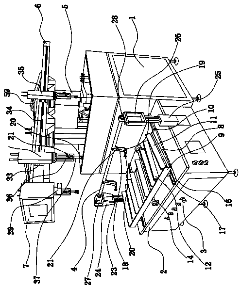
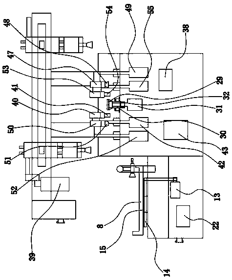
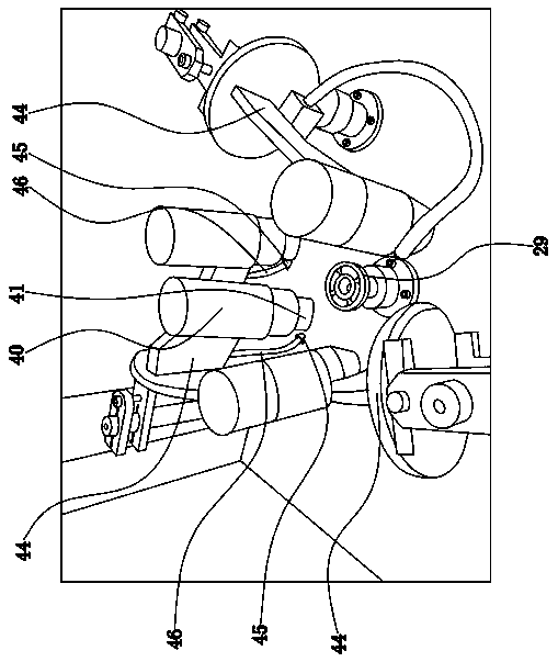
[0028] Such as figure 1 , figure 2 , image 3 and Figure 4As shown, the edging machine with a manipulator used for processing rearview mirror lenses is mainly composed of a main body 1 and an auxiliary body 2. There is a control cabinet 3 under the sub-body 2, and a central processing unit is controlled in the control cabinet 3. For the operation of the whole machine, a feeding tray is arranged horizontally on the table of the auxiliary body 2 parallel to the table of the auxiliary body 2, and a driving device for guiding and sliding the feeding tray is provided between the feeding tray and the 2 tables of the auxiliary body; during actual manufacturing , the specific structure of the tray is as follows: it is mainly ...


PUM


Abstract

The invention provides a mechanical arm edge grinding machine for rearview mirror lens machining, and belongs to the technical field of mechanical equipment. The mechanical arm edge grinding machine solves the problem that an existing edge grinding machine is complex in structure, inaccurate in material conveying, small in material containing quantity and not elaborate in edge grinding and chamfering. According to the mechanical arm edge grinding machine for rearview mirror lens machining, a driving device enabling a material containing disc to do guide sliding is arranged between the materialcontaining disc and an auxiliary machine body, a material taking device is arranged on a connecting rod, a material placing structure is arranged on a table face of a main machine, the transverse beam is provided with a mechanical arm device to do material transferring between the material taking device and the material placing structure, and an edge grinding structure, an upper edge chamfering structure, a lower edge chamfering structure and a fine grinding structure are sequentially arranged on the positions, around the material placing structure, of the table face of the main machine body.The mechanical arm edge grinding machine is simple in structure, machine running is stable, material conveying is accurate, the material containing quantity is large, and edge grinding and chamferingare elaborate.

Description

technical field [0001] The invention belongs to the technical field of mechanical equipment, and relates to an edger with a manipulator for processing rearview mirror lenses. Background technique [0002] At present, the edging machine used by domestic enterprises that produce motorcycle rearview mirrors is a simple manual edging machine driven by an electric motor with a diamond grinding wheel. On the one hand, it has a relatively high labor intensity, and the glass dust produced is harmful to the human body. Due to the artificial unevenness of the hand-turned lens when grinding by hand, especially the straight edge of the special-shaped lens is difficult to grind on the disc grinding wheel, which directly affects the product quality; in response to the above situation, a car mirror appeared on the market. Fully automatic edging machine, such as the Chinese patent No.: "201120484432.6", mainly includes the outer box of the machine body, the control electric cabinet, the sol...

Claims


Application Information

Patent Timeline
Patent Type & Authority Patents(China)
IPC IPC(8): B24B9/08B24B27/00B24B41/00B24B41/06B24B55/03
CPCB24B9/08B24B27/0076B24B41/005B24B41/06B24B55/03
Inventor 许建强
Owner 台州市星煜车辆部件有限公司
Learn More