Orthotropic steel-ultra high performance concrete bridge deck structure and its construction method

An ultra-high-performance, orthotropic technology, applied in bridges, bridge materials, bridge construction, etc., can solve problems such as roof and longitudinal ribs, longitudinal ribs and diaphragm fatigue cracking, etc., to achieve fatigue cracking, reliable connection, The effect of simple structure

Active Publication Date: 2021-05-18
CHINA MAJOR BRIDGE ENERGINEERING
View PDF7 Cites 0 Cited by
  • Summary
  • Abstract
  • Description
  • Claims
  • Application Information

AI Technical Summary

Problems solved by technology

[0006] The technical problem to be solved by the present invention is the problem of fatigue cracking at the roof and longitudinal ribs, longitudinal ribs and diaphragms in the existing orthotropic steel-ultra high performance concrete bridge deck structure and its construction method

Method used


Image

  • Orthotropic steel-ultra high performance concrete bridge deck structure and its construction method
  • Orthotropic steel-ultra high performance concrete bridge deck structure and its construction method
  • Orthotropic steel-ultra high performance concrete bridge deck structure and its construction method

Examples


specific Embodiment 1

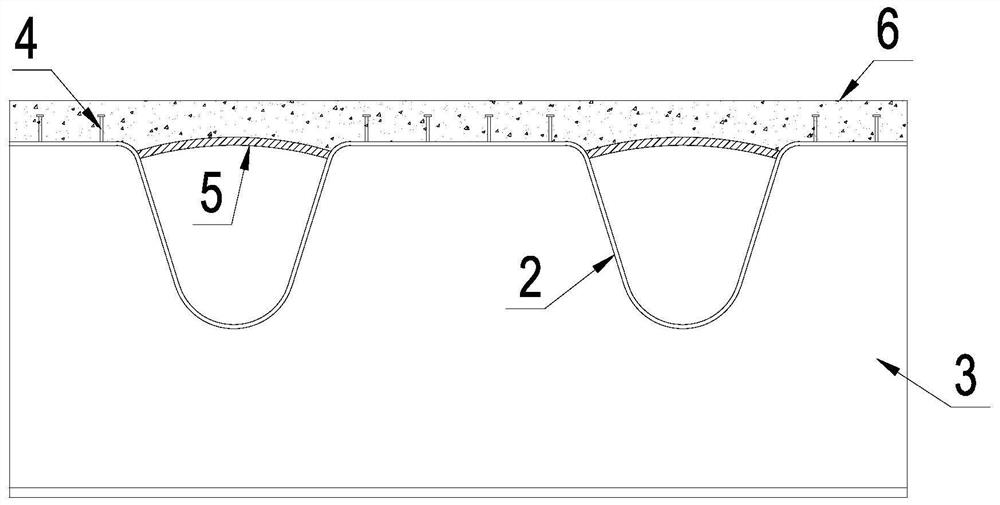
[0043] Such as figure 2 As shown, the prefabricated ultra-high-performance concrete layer 5 is arranged in the upper notch of the U-shaped groove, and the cast-in-place ultra-high-performance concrete layer 6 is arranged above the prefabricated ultra-high-performance concrete layer 5 and covers the top of the longitudinal rib 2 face. During the construction process, firstly, a prefabricated ultra-high performance concrete layer 5 is placed in the U-shaped notch as a base form, and the ultra-high performance concrete layer 6 is formed by pouring again.

specific Embodiment 2

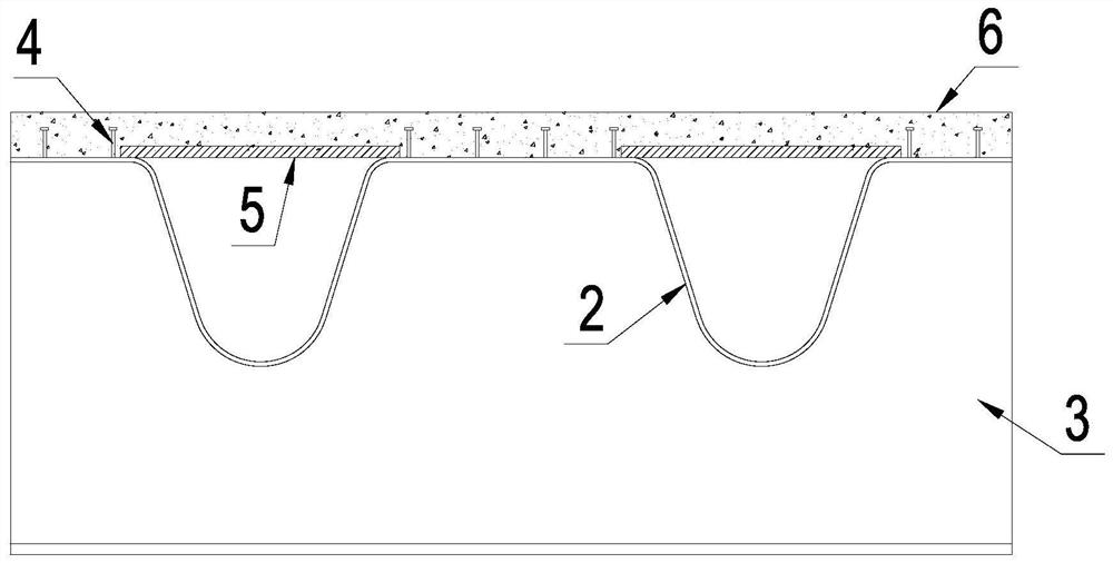
[0045] Such as image 3 As shown, the structure of its ultra-high performance concrete bridge deck 1, longitudinal rib 2, diaphragm 3 and shear connector 4 is the same as that of the specific embodiment 1, the difference is that the prefabricated ultra-high performance concrete layer 5 is a slab shape, and its bottom surface is flush with the upper end surface of the U-shaped notch.

specific Embodiment 3

[0047] Such as Figure 4 As shown, the prefabricated ultra-high performance concrete layer 5 is set on the top of the U-shaped groove, and the cast-in-place ultra-high performance concrete layer 6 is set on both sides of the prefabricated ultra-high performance concrete layer 5, and its top surface is the same as the prefabricated ultra-high performance concrete layer. The top surface of the concrete layer 5 is flush.

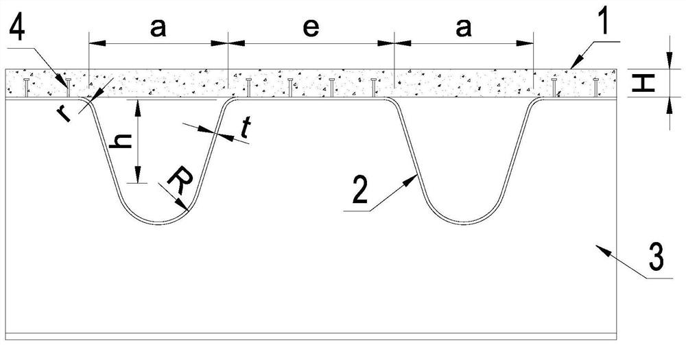
[0048]In the present invention, in order to increase the strength, several steel bars are embedded in the ultra-high performance concrete bridge deck 1 and arranged in a net shape. Preferably, the thickness H of the ultra-high performance concrete bridge deck 1 is 8-15 cm. Between the U-shaped grooves on the longitudinal ribs 2 is a horizontal part, the bottom of the U-shaped grooves is arc-shaped, and the notches are connected to the horizontal parts of the longitudinal ribs 2 through arc chamfering. Preferably, the notch width a of the U-shaped groove is 40...


PUM


Abstract

The invention discloses an orthotropic steel-ultra-high-performance concrete bridge deck structure and a construction method thereof, wherein the orthotropic steel-ultra-high-performance concrete bridge deck includes longitudinal ribs, transverse diaphragms and ultra-high-performance concrete bridge decks, There are multiple U-shaped grooves arranged along the length of the longitudinal ribs. The transverse diaphragm is welded to the bottom of the longitudinal ribs and arranged in multiple intervals. The ultra-high performance concrete bridge deck is set on the The top of the longitudinal ribs, which include a precast ultra-high performance concrete layer and a cast-in-situ ultra-high performance concrete layer. The invention cancels the cutouts on the steel roof and the longitudinal ribs used to connect with the transverse diaphragm, and through the U-shaped groove opening on the longitudinal ribs, it has the characteristics of high torsional rigidity and small torsional deformation, and can effectively reduce the longitudinal ribs. Risk of fatigue cracking at the weld to the diaphragm.

Description

technical field [0001] The invention relates to the technical field of bridge engineering, in particular to an orthotropic steel-ultra-high-performance concrete bridge deck structure and a construction method thereof. Background technique [0002] Orthotropic steel bridge decks have many advantages such as light weight, high strength, wide applicability, and fast construction speed, so they are widely used in long-span bridges. However, its structure is complex and there are many welds. Because it directly bears the repeated action of local vehicle wheel loads, its fatigue damage problem is very prominent in this field. [0003] Japan has investigated about 7,000 bridge engineering examples and found that among the orthotropic steel bridge decks using U ribs, the annular weld damage of the cutout part of the longitudinal ribs and diaphragms is the most, accounting for 38.2% of the whole. The welding part of the top plate and vertical ribs is next, accounting for 31.5% of th...

Claims


Application Information

Patent Timeline
Patent Type & Authority Patents(China)
IPC IPC(8): E01D19/12E01D21/00E01D101/24
CPCE01D19/125E01D21/00E01D2101/268
Inventor 肖海珠何东升胡文军康晋董学智梅大鹏
Owner CHINA MAJOR BRIDGE ENERGINEERING
Why Eureka
Try Eureka