
Cold chain vehicle waste heat synergistic mechanical-pump-free compression-injection refrigeration circulation system and method

A refrigeration cycle and circulation system technology, which is applied in the field of cold chain vehicle waste heat efficiency enhancement without mechanical pump compression-jet refrigeration cycle system, can solve the problems of reducing the transportation efficiency of cold chain vehicles, decreasing energy utilization efficiency, and decreasing battery life. Improve energy utilization efficiency and battery life, improve energy utilization efficiency, and improve the effect of energy utilization

Inactive Publication Date: 2018-10-16
HUAZHONG UNIV OF SCI & TECH
View PDF4 Cites 1 Cited by
  • Summary
  • Abstract
  • Description
  • Claims
  • Application Information

AI Technical Summary

Problems solved by technology

Although the two forms are different, the direct source of energy consumption of the refrigeration system is electrical energy or mechanical energy as a high-grade energy source. The electrical energy comes from the generator of the cold chain vehicle, and the mechanical energy comes from the consumption of the shaft power of the engine. The fuel of the cold chain vehicle is used for energy supply, which inevitably leads to the refrigeration system of the cold chain vehicle competing with the engine of the cold chain vehicle for fuel, which leads to a decrease in its battery life and reduces the overall transportation efficiency of the cold chain vehicle
[0003] During the normal driving process of the cold chain vehicle, the exhaust gas discharged by the engine carries a large amount of available heat, which is called waste heat. The heat energy carried by the engine exhaust gas is equivalent to about 50% of the total energy provided by the fuel, and this part of waste heat Most of the low-grade heat energy carried is directly discharged into the atmosphere without being fully utilized, resulting in a decrease in energy utilization efficiency

Method used


Image

  • Cold chain vehicle waste heat synergistic mechanical-pump-free compression-injection refrigeration circulation system and method
  • Cold chain vehicle waste heat synergistic mechanical-pump-free compression-injection refrigeration circulation system and method

Examples


Embodiment Construction

[0023] In order to make the object, technical solution and advantages of the present invention clearer, the present invention will be further described in detail below in conjunction with the accompanying drawings and embodiments. It should be understood that the specific examples described here are only used to explain the present invention, not to limit the present invention. In addition, the technical features involved in the various embodiments of the present invention described below can be combined with each other as long as they do not constitute a conflict with each other.

[0024] Most of the existing cold chain on-board refrigeration systems only use a single-stage vapor compression refrigeration cycle driven by electrical energy or mechanical energy. Both electrical energy and mechanical energy are high-grade energy sources, and ultimately come from the fuel consumption of the cold chain vehicle. It will inevitably cause the refrigeration system to compete with the ...


PUM


Abstract

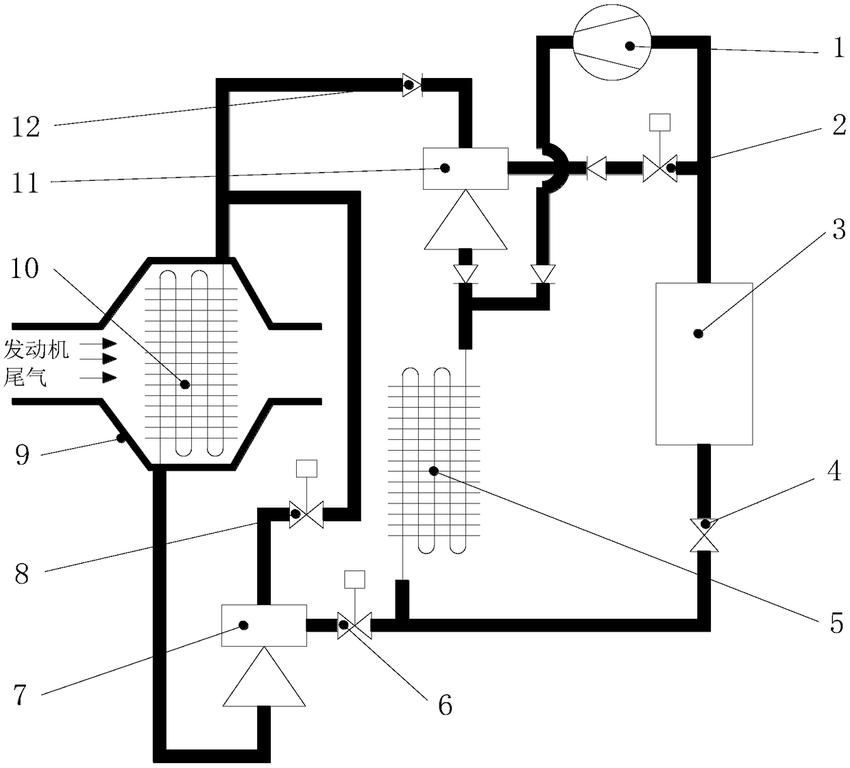
The invention belongs to the technical field of refrigeration circulation, and particularly discloses a cold chain vehicle waste heat synergistic mechanical-pump-free compression-injection refrigeration circulation system and method. The system comprises a steam compression refrigeration circulation module and a mechanical-pump-free injection refrigeration circulation module; the steam compressionrefrigeration circulation module comprises a compressor, a condenser, a throttling device and an evaporator, and is used for completing steam compression refrigeration circulation; and the mechanical-pump-free injection refrigeration circulation module comprises a generator, an ejector and a pressurization ejector, and is used for completing mechanical-pump-free injection refrigeration circulation. According to the system and method, on the basis of conventional steam compression refrigeration circulation of a cold chain vehicle, the mechanical-pump-free injection refrigeration circulation using waste heat of tail gas of an engine as the energy source is arranged, the energy is completely derived from the waste heat of the tail gas, any other external energy source supplies does not needso that the refrigerating capacity of the system can be greatly improved without loss of energy such as fuel oil, and then the energy utilization efficiency and the cruising ability of the cold chainvehicle are improved.

Description

technical field [0001] The invention belongs to the technical field of refrigerating cycles, and more specifically relates to a compression-injection refrigerating cycle system and method for waste heat enhancement of a cold chain vehicle without a mechanical pump. Background technique [0002] In the modern logistics industry, in order to meet the service needs of the high-end logistics industry, the cold chain transportation system focuses on realizing the whole-process frozen and fresh-keeping transportation service of the transported products from the production base to the sales customer, and the key core of the cold chain transportation technology The technology is the on-board refrigeration system, and the key core technology of the on-board refrigeration system is refrigeration technology. In the current cold chain vehicle-mounted refrigeration system, the conventional vapor compression refrigeration cycle is usually used, and the cold chain vehicle-mounted refrigera...

Claims


Application Information

Patent Timeline
Patent Type & Authority Applications(China)
IPC IPC(8): F25B25/00F25B27/02
CPCY02A30/274F25B25/00F25B27/02
Inventor 蔡德华邓佳驹何国庚梁翛周赛
Owner HUAZHONG UNIV OF SCI & TECH
Learn More