Automatic clustering separation method for multi-source partial discharge signals
A discharge signal and separation method technology, applied in the direction of measuring electricity, measuring electrical variables, testing dielectric strength, etc., can solve problems such as inability to perform correct diagnosis and disappearance of statistical features, so as to facilitate identification and diagnosis, improve effectiveness, Applicable to a wide range of effects
- Summary
- Abstract
- Description
- Claims
- Application Information
AI Technical Summary
Problems solved by technology
Method used
Image
Examples
Embodiment 1
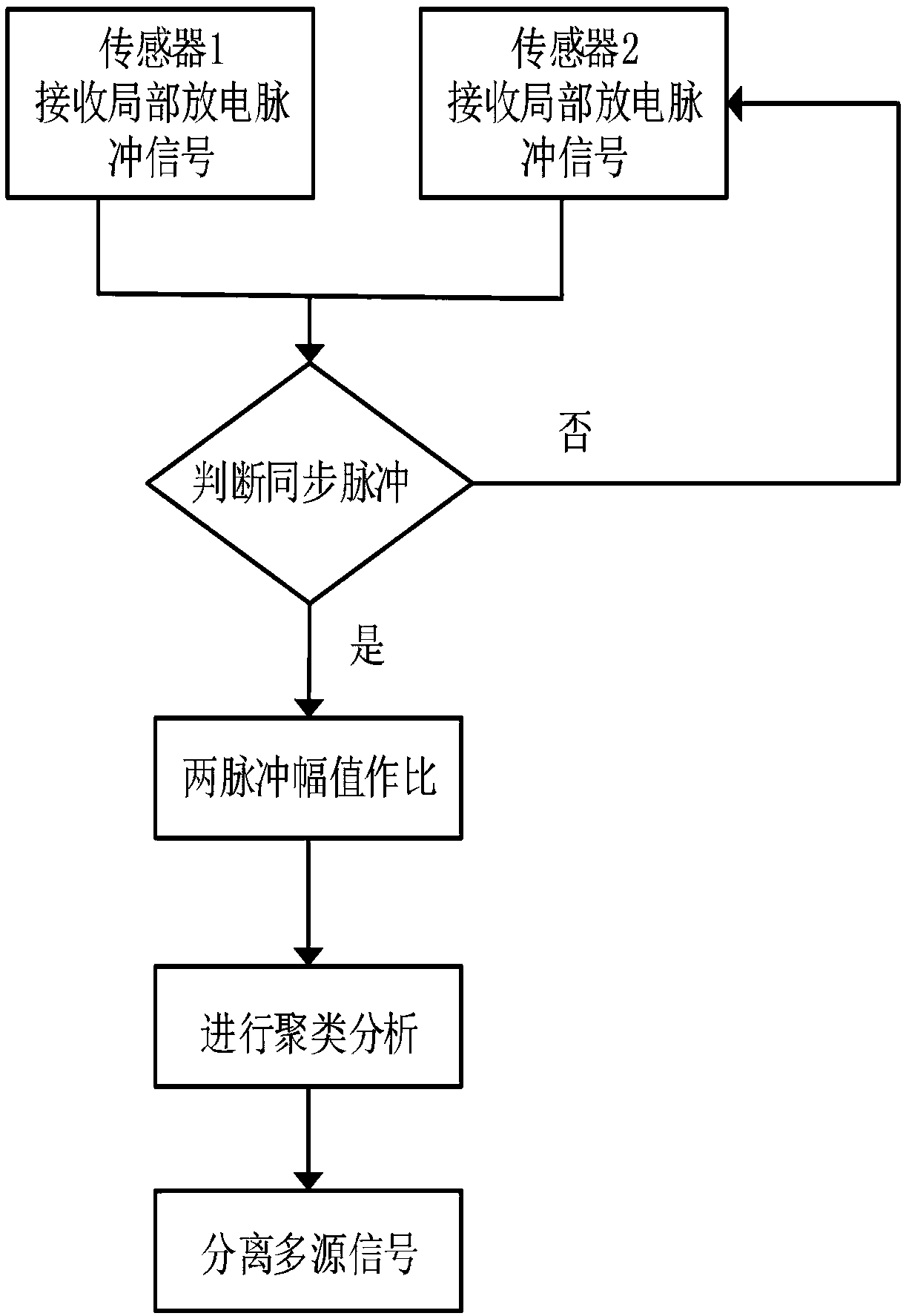
[0034] In this embodiment, two sensors are installed, such as figure 1 Shown is the flow diagram of the present invention to realize the method for automatic clustering and separation of multi-source partial discharge signals, and its specific steps are as follows:
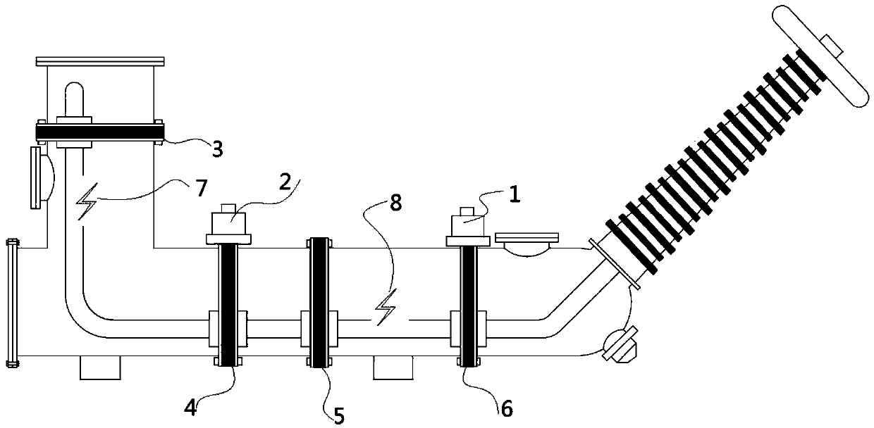
[0035] Step 1: Synchronously detect the partial discharge signal through the first sensor 1 and the second sensor 2 installed in different positions, and obtain its amplitude Vi and phase
[0036] Step 2: Judgment of the synchronous pulse of the partial discharge signal detected by the first sensor 1 and the second sensor 2, the judgment method is when the phase difference of the detected partial discharge signal pulse , it is considered as a synchronous signal;
[0037] Step 3: If it is a synchronous pulse, extract the synchronous signal pulse data from all partial discharge signals detected in step 1;
[0038] Step 4: Calculate the amplitude ratio Ri of all synchronous signal pulses on the time domain wavef...
Embodiment 2
[0050] This embodiment simulates the spike discharge in the air and the interference of fluorescent lamps. After the test power supply passes through the isolation transformer T 0 After voltage regulation output, connect to 110kV test transformer, transformer T 0 It is used to realize the electrical isolation of the high-voltage test circuit and the low-voltage power supply circuit, and prevent the introduction of interference from the low-voltage power supply side. After the outgoing line of the test transformer 11 passes through the protective resistor, the end is connected to a smooth metal guide rod 15 for placing discharge models, including a suspension discharge model 12 and a spike discharge model 13 . The sharpened copper wire is fixed on the metal guide rod to form a spike discharge, and the fluorescent lamp discharge simulates the interference discharge source, such as Figure 5 As shown, the distance between the third sensor 9 and the fourth sensor 10 is 5 meters. ...
PUM
 Abstract
Description
Claims
Application Information
 - R&D
- Intellectual Property
- Life Sciences
- Materials
- Tech Scout
- Unparalleled Data Quality
- Higher Quality Content
- 60% Fewer Hallucinations
Browse by: Latest US Patents, China's latest patents, Technical Efficacy Thesaurus, Application Domain, Technology Topic, Popular Technical Reports.
© 2025 PatSnap. All rights reserved.Legal|Privacy policy|Modern Slavery Act Transparency Statement|Sitemap|About US| Contact US: help@patsnap.com


