Voice coil motor and manufacturing method thereof

A technology of a voice coil motor and a manufacturing method, which is applied in the field of cameras, can solve the problems of increasing solder paste, increasing the consumption of glue consumables, and increasing the huge risk of foreign matter generated by flux, so as to improve production efficiency and cost, avoid consumption of glue consumables, The effect of avoiding the problem of glue cracking

Pending Publication Date: 2018-10-16
深圳市丘钛微电子科技有限公司
View PDF10 Cites 2 Cited by
  • Summary
  • Abstract
  • Description
  • Claims
  • Application Information

AI Technical Summary

Problems solved by technology

[0004] First, when the coil is electrically connected to the lower spring, the surface of the coil has an insulating enamel coating, which requires the winding supplier to remove the enamel coating, or the voice coil motor factory arranges labor or equipment removal by itself, which will increase the cost and process. If If it is manual removal, it will have higher requirements for operators, and it is more difficult to train personnel
Solder paste soldering is required after removing the enamelled layer, which increases the solder paste and increases the cost of raw materials
Moreover, after adding solder paste, it also increases the huge risk of foreign matter generated by the flux, which leads to the need to add liquid medicine for cleaning in the subsequent process
Some manufacturers use the resistance welding method, which also requires the size of the carrier pad, which makes it difficult to miniaturize the motor
[0005] Second, if the coil and the lower spring are welded without removing the enamelled layer, and other welding methods are used, the staff will need to tidy up the thread ends, resulting in increased labor costs. Staff resignation will lead to a significant drop in production line yield and efficiency
[0006] Thirdly, the solder joints between the coil and the lower spring are leaking. The current process requires encapsulation, otherwise there will be foreign matter problems. At the same time, the solder joints cannot be guaranteed to be stable for a long time, which increases the difficulty of the process and increases the consumption of glue consumables.
[0007] Fourth, the line between the welding point of the coil and the lower spring and the coil body is very easy to disconnect during the reliability test, resulting in a bad open circuit of the voice coil motor
[0008] Fifth, the connection between the lower spring piece and the carrier also requires glue bonding, or hot riveting, or glue and hot riveting at the same time, which increases the complexity of the process and increases the cost of glue consumption
[0009] Sixth, the traditional production process requires a large number of fixtures, which also results in higher costs
[0010] Seventh, the traditional process is that the carrier is first injection molded, and then the coil is wound on the carrier, which will cause a drastic change in torque, which has higher requirements for carrier molding manufacturers and winding manufacturers
At the same time, it also increases the difficulty of control for VCM autofocus motor manufacturers

Method used


Image

  • Voice coil motor and manufacturing method thereof
  • Voice coil motor and manufacturing method thereof
  • Voice coil motor and manufacturing method thereof

Examples


no. 1 example

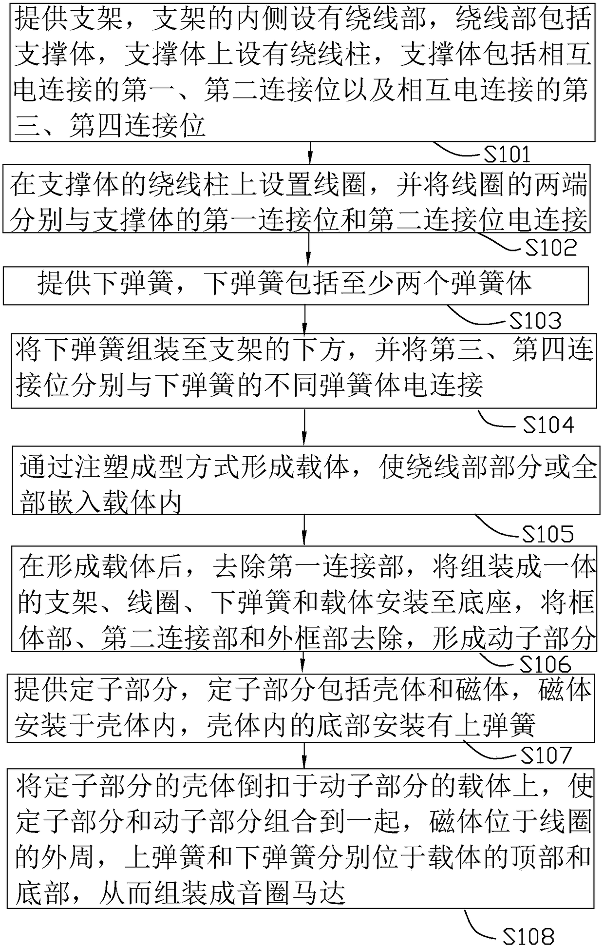
[0072] Such as figure 1 As shown, it is a flowchart of a method for manufacturing a voice coil motor provided in the first embodiment of the present invention. The method for manufacturing a voice coil motor in this embodiment includes the following steps:

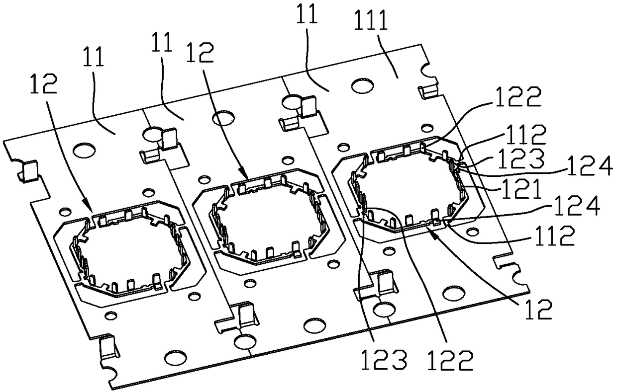
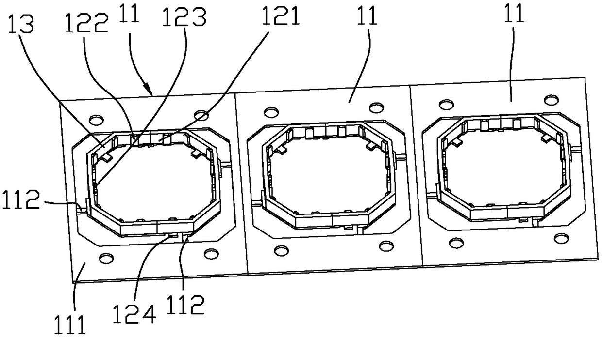
[0073] S101 , provide the bracket 11 , the inner side of the bracket 11 is provided with a winding part 12 , the winding part 12 includes a support body 121 divided into two parts, each part of the support body 121 is provided with a winding post 122 . The support body 121 includes a first connection position and a third connection position electrically connected to each other, and a second connection position and a fourth connection position electrically connected to each other. The first connection position and the second connection position are respectively located in the separated two-part support body 121 on.

[0074] In this example, if figure 2 As shown, the number of brackets 11 is multiple and connected as long...

no. 2 example

[0114] Such as Figure 11 As shown, it is a flowchart of a manufacturing method of a voice coil motor provided by the second embodiment of the present invention. The difference between this embodiment and the above-mentioned first embodiment is that in this embodiment, the winding part 12 and the lower spring 15 The plurality of spring bodies 151 are integrated, that is, the winding part 12 is directly integrated with the plurality of spring bodies 151, but in the above-mentioned first embodiment, the plurality of spring bodies 151 of the winding part 12 and the lower spring 15 are The structure is divided into two parts and the electrical connection is realized by welding between the conductive terminals 154 and 124 .

[0115] The manufacturing method of the voice coil motor of this embodiment includes the following steps:

[0116] S201, such as Figure 12 As shown, a lower spring 15 is provided. The lower spring 15 includes a plurality of spring bodies 151, and a winding p...

no. 3 example

[0147] Such as Figure 2 to Figure 10 and Figure 12-Figure 13 As shown, the third embodiment of the present invention provides a voice coil motor, including:

[0148] The winding part 12, the winding part 12 includes two support bodies 121 spaced apart from each other, and each support body 121 is provided with a winding post 122;

[0149] The coil 13 is arranged on the winding posts 122 of the two supports 121, and the two ends of the coil 13 are respectively electrically connected to the two supports 121;

[0150] The lower spring 15, the lower spring 15 includes a plurality of spring bodies 151 spaced apart from each other, the winding part 12 and the plurality of spring bodies 151 are all made of conductive materials, and the two supporting bodies 121 are different from the different spring bodies 151 of the lower spring 15 respectively. Electrical connection; it can be understood that the number of spring bodies 151 can be at least two.

[0151] The carrier 17 , the w...


PUM


Abstract

The invention discloses a voice coil motor and a manufacturing method thereof. The manufacturing method of the voice coil motor comprises the steps of providing winding parts, wherein each winding part comprises a support body, and winding columns are arranged on the support body; providing a lower spring, wherein the lower spring comprises at least two spring bodies, and the third connecting position and the fourth connecting position of the support body are electrically connected with different spring bodies of the lower spring respectively; setting a coil on the winding columns of the support body, and enabling the two ends of the coil to be electrically connected with the first connecting position and the second connecting position of the support body respectively; and forming a carrier in an injection molding manner. According to the voice coil motor and the manufacturing method thereof, the coil is electrically connected with the winding parts, and then the winding parts are electrically connected with the lower spring, so that conduction connection between the coil and the lower spring is realized, removal of a varnished wire of the coil is not needed, wire end arrangement by the working staff is avoided, production efficiency is improved and cost is lowered, the problem of exposure of a welding point is avoided, long lasting and firmness of the welding point can be ensured, process difficulty is lowered, and consumption of glue consumable material caused by rubber coating processing can be avoided.

Description

technical field [0001] The invention relates to the field of camera technology, in particular to a method for manufacturing a voice coil motor and the voice coil motor. Background technique [0002] Along with the progress of science and technology, the application of camera is more and more extensive, at present, except camera, mobile phone, computer and other electronic products are all equipped with camera, to facilitate people to take pictures anytime and anywhere, to bring convenience and fun to people's life. [0003] At present, in the production of auto-focus voice coil motors, the carrier and the lower spring are generally formed first, and then the coil is wound on the carrier, and then the end of the coil is electrically connected to the Lower the spring leaf and fix the lower spring leaf. However, this production method has the following problems: [0004] First, when the coil is electrically connected to the lower spring, the surface of the coil has an insulat...

Claims


Application Information

Patent Timeline
Patent Type & Authority Applications(China)
IPC IPC(8): H02K41/035
CPCH02K41/0356
Inventor 潘涛
Owner 深圳市丘钛微电子科技有限公司
Why Eureka
Try Eureka