
Latch circuit

A latch circuit, latch technology, applied in the direction of analog-to-digital converter, reliability improvement and modification, etc., can solve the problem of high contribution ratio of analog-to-digital converter, reduction of resolution of analog-to-digital converter, and reduction of comparator Bit resolution, etc.

Inactive Publication Date: 2018-10-16
SHANGHAI HUALI INTEGRATED CIRCUTE MFG CO LTD
View PDF7 Cites 5 Cited by
  • Summary
  • Abstract
  • Description
  • Claims
  • Application Information

AI Technical Summary

Problems solved by technology

In this way, the contribution of M3 and M4 to the voltage mismatch of the comparator is increased, and the bit resolution of the comparator is reduced.
At the same time, the two input tubes of M1 and M2 are in the linear region, which will provide a relatively low amplification gain, and the overall working speed of the comparator will be greatly affected.
[0004] It can be seen that the StrongARM latch circuit of the prior art has the following defects: the working time of the comparator is long, and the contribution of the bit error rate (Bit Error Rate) in the design of the analog-to-digital converter (ADC) is high. Mismatch has a large impact on comparison accuracy
For the design of high-speed analog-to-digital converters, these defects are particularly prominent, which will affect the signal establishment accuracy and reduce the resolution of the analog-to-digital converter (ADC) under the same working time

Method used


Image

  • Latch circuit
  • Latch circuit
  • Latch circuit

Examples


Embodiment Construction

[0046] The circuit composition and connection mode of the present invention are further described in conjunction with the drawings and specific embodiments, and the beneficial effects of the present invention are also illustrated.

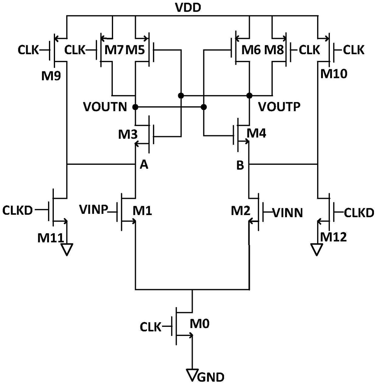
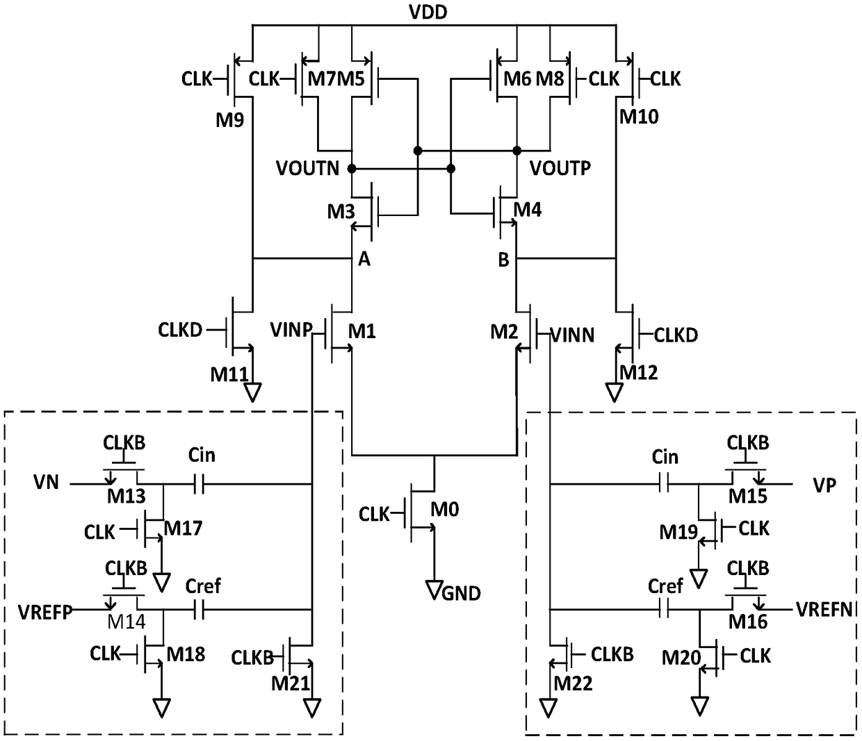
[0047] Such as figure 2 As shown, a latch circuit provided by the present invention includes: a current tail pipe—a third NMOS transistor (M0); the preamplifier consists of a fourth NMOS transistor (M1) and a fifth NMOS transistor (M2) The gates of the fourth NMOS transistor (M1) and the fifth NMOS transistor (M2) are connected to the differential signal VINN and VINP, and the differential signal is amplified to the A and B terminals; the main body of the comparison latch includes A CMOS comparison latch, the CMOS comparison latch is composed of the fifth PMOS transistor (M5), the sixth PMOS transistor (M6), the sixth NMOS transistor (M3), and the seventh NMOS transistor (M4). The latch latches the amplified differential signal. The aforementioned...


PUM


Abstract

The invention relates to a latch circuit. The latch circuit comprises a preamplifier, a comparison latch body, a first pair of reset tubes, a second pair of reset tubes, and a pair of switch tubes, wherein the preamplifier amplifies an input differential signal, the comparison latch body is connected with the preamplifier and performs compared latch on the amplified differential signal, the firstpair of reset tubes are connected with an output of the comparison latch body and a power supply, the second pair of reset tubes are connected with a drain of an input pair tube of the preamplifier and a power supply, the drain of the input pair tube of the preamplifier is grounded through the pair of switch tubes, gates of the two pairs of reset tubes receive a clock signal, a gate of the pair ofswitch tubes receives a delayed clock signal of the clock signal, the two pairs of reset tubes are used for enabling the comparison latch body to work in a linear area when the clock signal changes from low to high, and the pair of switch tubes helps reduce one tube for the ground path of the comparison latch body in work. The impact of circuit mismatch on comparison accuracy is lowered, the working time of a comparator is reduced, and the bit error rate in design of an analog-to-digital converter caused by the latch comparator is lowered.

Description

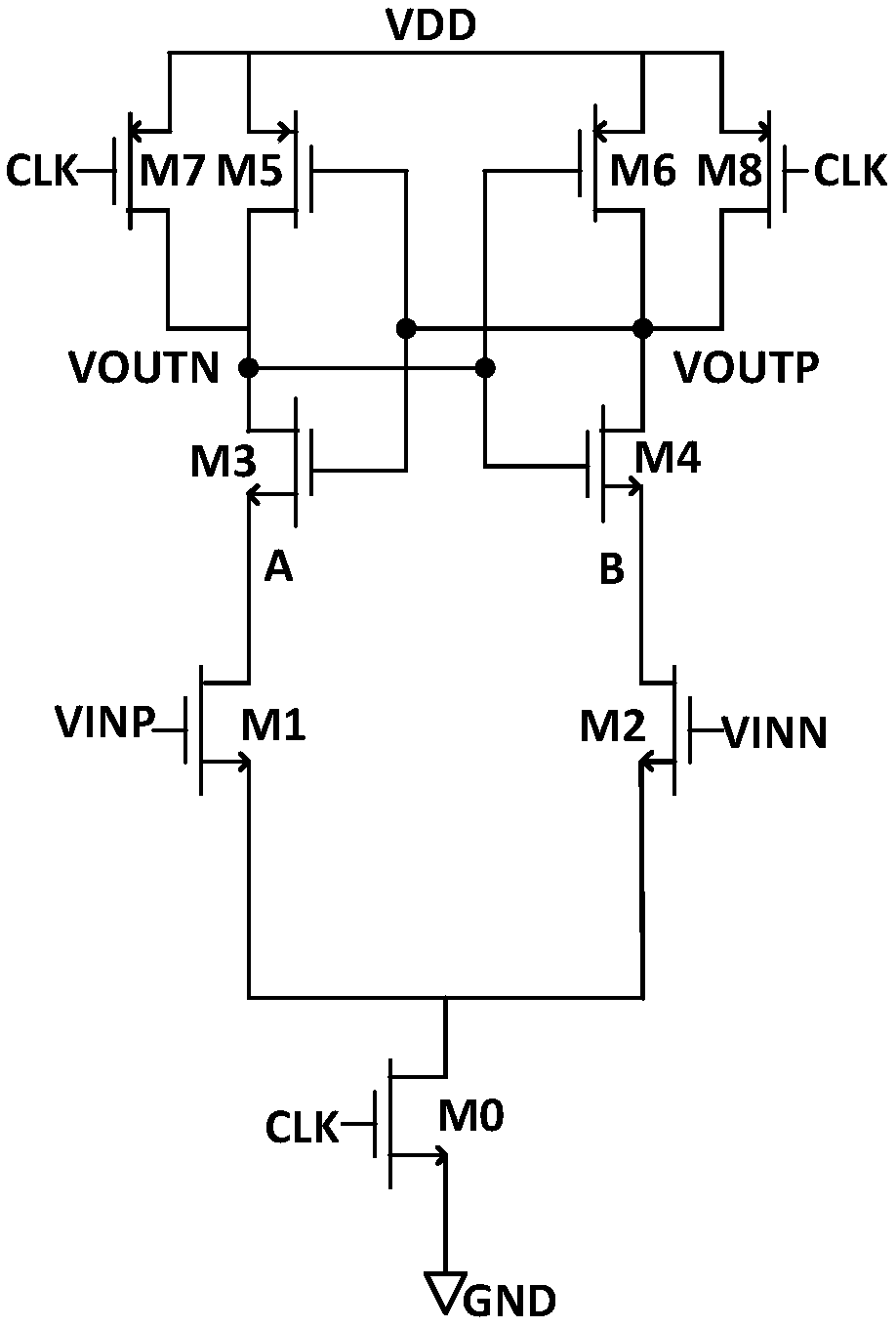
technical field [0001] The invention relates to the field of CMOS integrated circuit design, in particular to a novel StrongARM latch circuit with enhanced speed and reduced mismatch. Background technique [0002] see figure 1 As shown, the StrongARM latch circuit in the prior art mainly has two working states (the English full name of StrongARM is Strong Advanced RISC Machine, which supports the RISC of WinCE3.0-PocketPC system—the processor of the reduced instruction set.) When CLK When it is low, the current tail tube M0 is disconnected, M7 and M8 reset the two outputs of VOUTP and VOUTN and pull them high, and the latch is in the output reset state. When CLK is high, the current tail tube M0 is turned on, and the input pair tubes M1 and M2 amplify the input signals VINP and VINN and introduce them into the two circuit nodes of A and B, and then pass them into the upper CMOS latch composed of M3-M6 for processing. Compare latches. [0003] This structure is a classic d...

Claims


Application Information

Patent Timeline
IPC IPC(8): H03K19/003H03M1/12
CPCH03K19/003H03M1/12
Inventor 张宁邱雯婷
Owner SHANGHAI HUALI INTEGRATED CIRCUTE MFG CO LTD
Learn More