Metal casting blank continuous manufacturing device and method capable of providing pressure casting

A manufacturing device and metal technology, which is applied in the field of continuous manufacturing devices for metal billets that can provide pressure casting, can solve the problems affecting the quality of billets and the inability to effectively control the melting temperature, etc., achieve continuous preparation, improve the quality of molten iron, and increase the use of The effect of longevity

Inactive Publication Date: 2018-10-19
HUNAN CITY UNIV
View PDF7 Cites 6 Cited by
  • Summary
  • Abstract
  • Description
  • Claims
  • Application Information

AI Technical Summary

Problems solved by technology

However, the existing metal slab continuous manufacturing devices cannot effectively control the melting temperature, and sometimes some incompletely melted metal residues or other substances are die-casted into the slab during the continuous casting process, which will greatly affect the quality of the slab. quality

Method used


Image

  • Metal casting blank continuous manufacturing device and method capable of providing pressure casting
  • Metal casting blank continuous manufacturing device and method capable of providing pressure casting

Examples


Embodiment 1

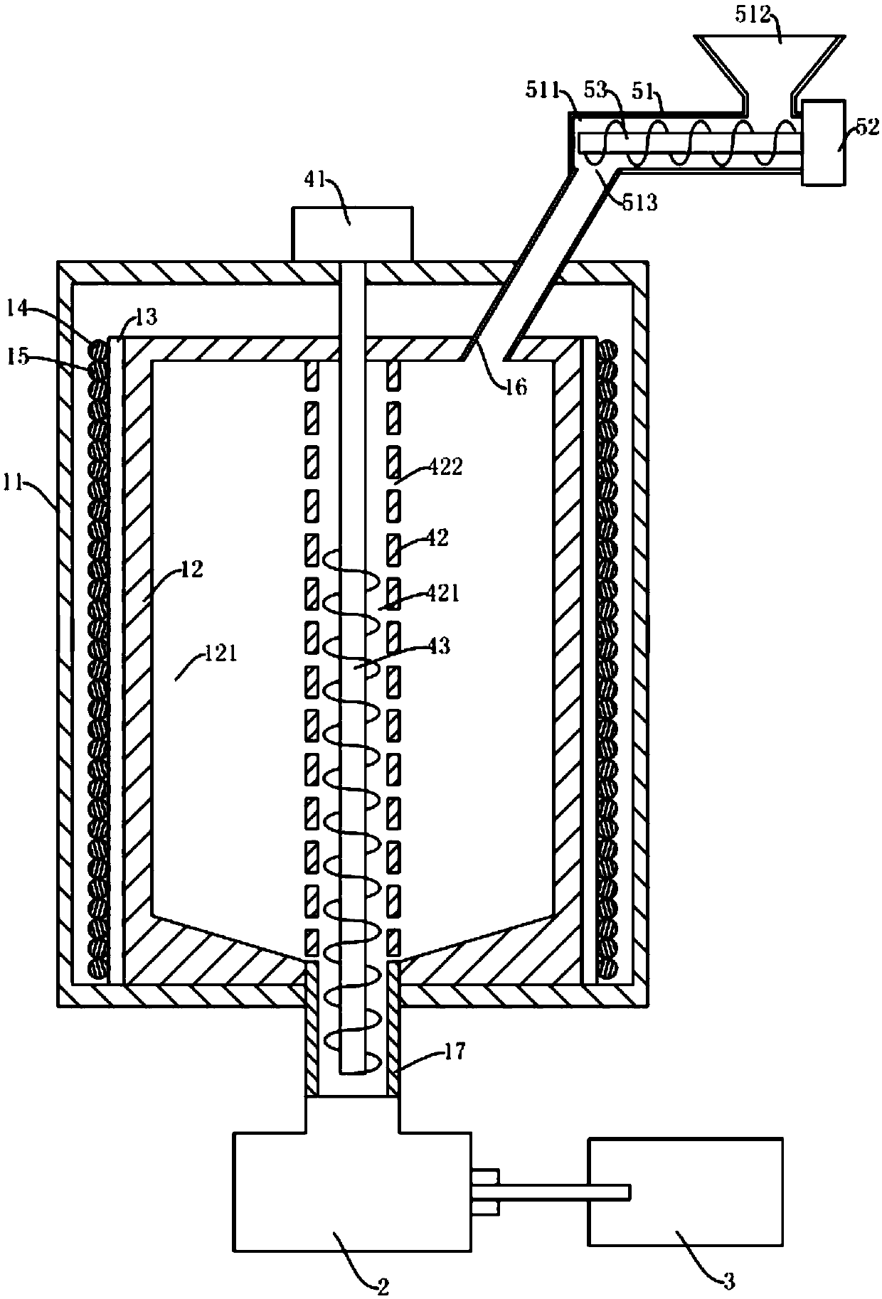
[0062] A method for continuously manufacturing aluminum alloy rod blanks with a diameter of 8 mm. First, the electromagnetic heating controller is started to preheat the crucible 12 for 10 minutes, and the temperature in the melting chamber 121 is monitored by a temperature sensor until the temperature in the melting chamber 121 reaches 500° C.; the feeding motor 52 and the propeller 53 are started. Turn the material in the material tank 512 into the melting chamber 121 through the feeding pipe 16, control the electromagnetic heating controller to increase the output power until the temperature in the melting chamber 121 reaches 1500 °C; half an hour later, start the propulsion motor 41 and crystallization Device 2, control the rotational speed of the screw rod 43 to less than 10r / min, start the traction mechanism to pull the aluminum alloy rod, and control the continuous or intermittent movement of the feeding motor 52 at the same time, so as to realize the continuous feeding o...

Embodiment 2

[0064] A continuous manufacturing method for a copper alloy rod billet with a diameter of 16 mm. Firstly, the electromagnetic heating controller is started to preheat the crucible 12 for 20 minutes, and the temperature in the melting chamber 121 is monitored by a temperature sensor until the temperature in the melting chamber 121 reaches 800° C.; the feeding motor 52 and the propeller 53 are started. Turn the material in the material tank 512 into the melting chamber 121 through the feeding pipe 16, control the electromagnetic heating controller to increase the output power until the temperature in the melting chamber 121 reaches 1800 °C; half an hour later, start the propulsion motor 41 and the crystallizer Device 2, control the rotating speed of the screw rod 43 to 15r / min, start the traction mechanism to pull the copper alloy rod, and control the continuous or intermittent movement of the feeding motor 52 at the same time, to realize the continuous feeding or intermittent fee...


PUM


Abstract

The invention discloses a metal casting blank continuous manufacturing device and method capable of providing pressure casting. The metal casting blank continuous manufacturing device comprises a smelting furnace, a crystallizer, a pushing-in mechanism, a pulling mechanism and a control system. The smelting furnace comprises a shell and a crucible arranged in the shell. A smelting cavity is formedin the crucible. The side wall of the crucible is sleeved with a thermal insulating layer. Electromagnetic heating rings and water cooling pipes are wound around the thermal insulating layer alternately. A discharge pipe is arranged on the lower portion of the crucible. One end of the discharge pipe communicates with the smelting cavity. The other end of the discharge pipe sequentially penetratesthrough the wall of the crucible and the wall of the shell and then communicates with a feed inlet of the crystallizer. The pulling mechanism is located behind a discharge outlet of the crystallizer,thereby being used for pulling a metal casting blank. The pushing-in mechanism is arranged in the smelting cavity, thereby being used for pushing smelted materials into the discharge pipe. An electromagnetic heating controller, a water chiller, the crystallizer, the pushing-in mechanism and the pulling mechanism are in control connection with the control system. The casting blank quality of the metal casting blank during continuous casting can be promoted effectively.

Description

technical field [0001] The invention relates to the technical field of metal casting, in particular to a continuous manufacturing device and method for metal casting slabs capable of providing pressure casting. Background technique [0002] Continuous casting is an advanced casting method. Its principle is to continuously pour molten metal into a special metal mold called a crystallizer, and the solidified (crusted) casting is continuously poured from the other end of the crystallizer. Pulled, it obtains castings of any length or a specific length. The development of continuous casting is an important means to optimize the structure of my country's metallurgical industry, which will fundamentally change the current situation of low efficiency and high consumption of metal material production in my country, and promote the development of product structure in the direction of specialization. The development of advanced continuous casting technologies such as near-net shape co...

Claims


Application Information

Patent Timeline
Patent Type & Authority Applications(China)
IPC IPC(8): B22D11/14B22D11/10
CPCB22D11/14B22D11/10
Inventor 曾琦高祥照唐杰
Owner HUNAN CITY UNIV
Why Eureka
Try Eureka