Grinding and polishing robot

A robot and polishing wheel technology, applied in the field of polishing, can solve problems such as high noise, lack of precision polishing, and difficulty in ensuring the consistency of processed workpieces

Pending Publication Date: 2018-10-19
江门市蓬江区科技中心
View PDF8 Cites 6 Cited by
  • Summary
  • Abstract
  • Description
  • Claims
  • Application Information

AI Technical Summary

Problems solved by technology

[0002] The existing grinding and polishing manipulator is suitable for all aspects of the grinding and polishing process of various types of workpieces and materials. Compared with the high efficiency of robotic automatic grinding and polishing, the polishing of conventional complex-shaped workpieces (such as aviation blades, pipe fittings, faucets, and precision castings) etc.) need to be done manually, and the main disadvantages of manual operation are as follows: 1. Low processing efficiency, manual operation, fatigue problems will occur; 2. It is difficult to guarantee product consistency, manual operation, there will be proficiency and technical level 3. The working environment of the production personnel is harsh, and the operator is always in a noisy and dusty working environment, which will cause harm to the human body; 4. The management cost is high, and the workers higher wage costs
For grinding and polishing robots, there are mainly grinding belt machine robots, grinding wheel machine robots, grinding and polishing machine robots, and grinding head robots in the current society. These models effectively solve the problem of robots replacing human hands in traditional grinding, but There are two major defects: 1. It only solves the rough grinding and polishing process, and cannot achieve the effect and purpose of precision polishing; 2. Each machine works independently and cannot be connected as a whole. Each station is operated separately, and the degree of automation and The degree of intelligence is not high enough

Method used


Image

  • Grinding and polishing robot

Examples


Embodiment Construction

[0013] The present invention will be further described in detail below in conjunction with the accompanying drawings and specific embodiments.

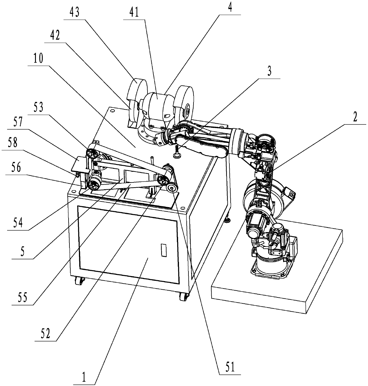
[0014] refer to figure 1 , a grinding and polishing robot of the present invention includes a polishing workbench 1 and a manipulator 2 that can move a workpiece. A working area 10 is arranged on the top, and a milling cutter 3 is arranged at the front end of the working area 10. A belt machine 5 and a polishing wheel mechanism 4 are respectively arranged on both sides of the milling cutter 3. The manipulator 2 is located on the polishing table 1 The front side of the milling cutter is close to 3 sides. When working, the conveying device transports the workpiece to the working area 10 of the polishing table 1, and then the manipulator 2 grabs and places the workpiece on the milling cutter 3 for surface milling, so that the size of the workpiece is more uniform before fine polishing, and then The manipulator 2 then grabs and moves th...


PUM


Abstract

The invention discloses a grinding and polishing robot. The grinding and polishing robot comprises a polishing workbench and a mechanical arm, wherein the mechanical arm is capable of moving a workpiece; a working area is arranged on the polishing workbench, milling cutters are arranged at the front end of the working area, and the two sides of the milling cutters are provided with a belt sander and a polishing wheel mechanism respectively; during operation, a conveying device conveys the workpiece to the working area on the polishing workbench, then the mechanical arm is used for grabbing andplaces the workpiece on the milling cutters to be subjected for surface milling, so that the size of the workpiece is more uniform before fine polishing; and then the mechanical arm moves the workpiece to the sanding belt machine for rough grinding of the surface, then the mechanical arm is used for grabbing and moving the workpiece to the polishing wheel mechanism for finish polishing, and grabbing the workpiece and placing the workpiece to the conveying device for being conveyed to the next working procedure after the polishing is finished. According to the grinding and polishing robot, through the above arrangement, fine polishing of the workpiece can be achieved, and the workpiece does not need to be clamped many times, the efficiency is high, and the practicability is relatively high.

Description

technical field [0001] The invention relates to the technical field of polishing, in particular to a grinding and polishing robot. Background technique [0002] The existing grinding and polishing manipulator is suitable for all aspects of the grinding and polishing process of various types of workpieces and materials. Compared with the high efficiency of robotic automatic grinding and polishing, the polishing of conventional complex-shaped workpieces (such as aviation blades, pipe fittings, faucets, and precision castings) etc.) need to be done manually, and the main disadvantages of manual operation are as follows: 1. Low processing efficiency, manual operation, fatigue problems will occur; 2. It is difficult to guarantee product consistency, manual operation, there will be proficiency and technical level 3. The working environment of the production personnel is harsh, and the operator is always in a noisy and dusty working environment, which will cause harm to the human b...

Claims


Application Information

Patent Timeline
Patent Type & Authority Applications(China)
IPC IPC(8): B24B27/00B24B41/00B25J11/00
CPCB24B27/0076B24B41/005B25J11/0065
Inventor 刘国炎
Owner 江门市蓬江区科技中心
Why Eureka
Try Eureka