Joint structure of second-lining end mold having sealing devices

A technology of joint structure and sealing device, applied in tunnel lining, tunnel, wellbore lining and other directions, can solve the problems of difficult cleaning, loose concrete at circumferential construction joints, and leakage of slurry, etc., to facilitate maintenance and replacement, and eliminate assembly. Error, avoid the effect of assembly gap

Pending Publication Date: 2018-10-19
CHINA RAILWAY SIYUAN SURVEY & DESIGN GRP
View PDF0 Cites 3 Cited by
  • Summary
  • Abstract
  • Description
  • Claims
  • Application Information

AI Technical Summary

Problems solved by technology

[0003] The traditional two-liner end formwork is assembled with wooden formwork to form a complete two-liner structure. After the assembled wooden formwork is sealed, the gap is large, which not only easily causes cement slurry leakage and loose concrete at the circumferential construction joints, but also affects the quality of the end concrete. , and the slurry flowing out from the joints of the wooden formwork is likely to cause pollution to the front inverted arch side wall, and it is difficult to clean;
[0004] In addition, the end formwork of the traditional secondary lining is close to the side of the initial support. In order to adapt to the unevenness of the surrounding rock surface on the surface of the primary sprayed concrete, the installation process of the traditional wooden formwork needs to be adjusted repeatedly. The efficiency is low, and the turnover of the wooden formwork is less. , the loss of each cutting wear is large; at the same time, the unevenness of the surrounding rock surface on the surface of the primary sprayed concrete between the second lining end mold and the primary lining will also cause the problem of grout leakage

Method used


Image

  • Joint structure of second-lining end mold having sealing devices
  • Joint structure of second-lining end mold having sealing devices
  • Joint structure of second-lining end mold having sealing devices

Examples


no. 1 example 1

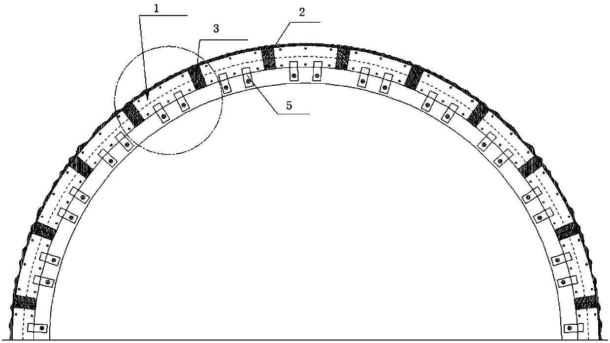
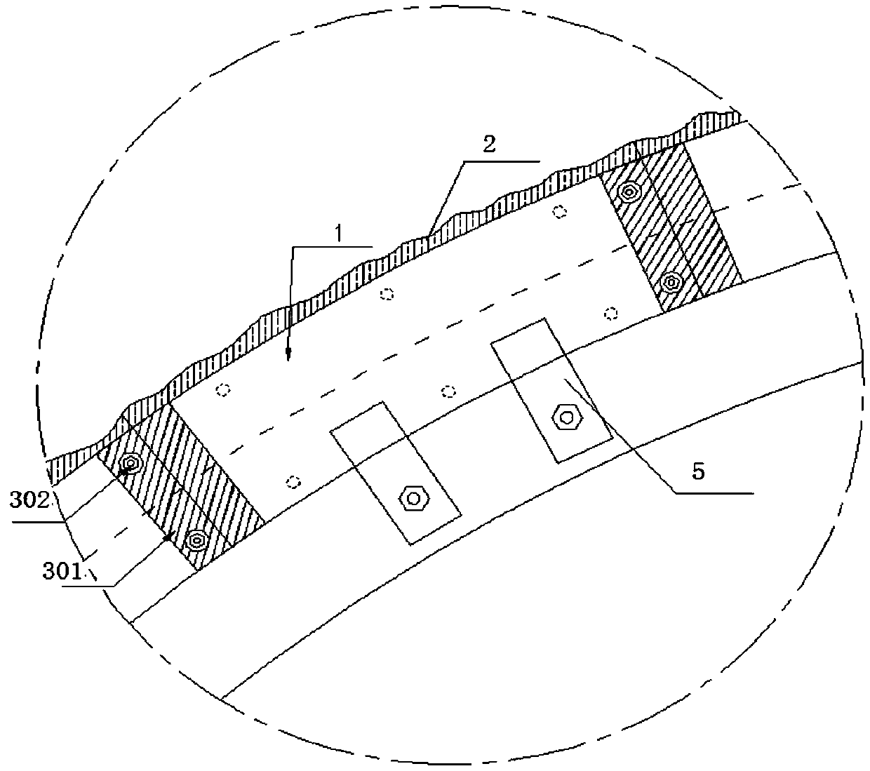
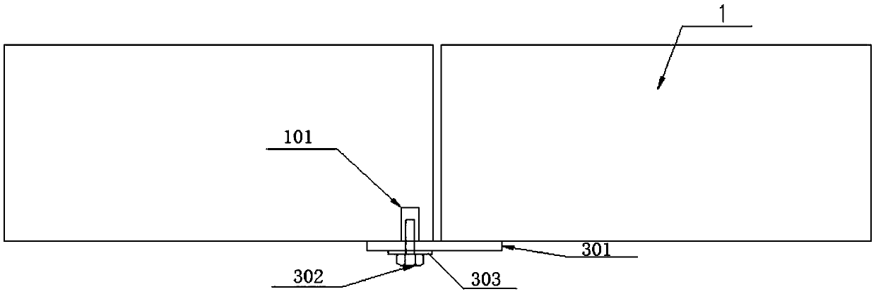
[0035] figure 1 It is a structural schematic diagram of a tunnel two-lined end die joint structure with a sealing device according to the first embodiment of the present invention. figure 2 for figure 1 A partial enlargement of the . image 3 It is a schematic structural diagram of the joint of the liner end die in the second embodiment of the present invention. Such as figure 1 , figure 2 and image 3 As shown, the joint structure of the second lining end mold of the tunnel includes an arc-shaped end mold 1, a first end mold slot joint 3 and an L-shaped fixing device. One side of the arc-shaped end mold 1 is fixed on the second lining platform by the L-shaped fixing device. On the car, wherein, the arc-shaped end molds 1 are several pieces, and the adjacent arc-shaped end molds 1 are assembled to form a combined and assembled two-liner structure; there are gaps in the assembly between the adjacent arc-shaped end molds, and the adjacent arc-shaped end molds 1 is provid...


PUM


Abstract

The invention discloses a joint structure of a second-lining end mold having sealing devices. The structure comprises multiple arc end molds (1) and L-shaped fixing devices (5). One sides of the L-shaped fixing devices (5) are fixed on the arc end molds (1) and the other sides thereof are fixed onto a second-lining trolley. Adjacent arc end molds (1) are spliced to form the second-lining end mold.End-mold clamping groove joints, detachably connected, are arranged between adjacent arc end molds (1). One ends of the end-mold clamping groove joints are arranged on one arc end mold (1) and the other ends thereof are arranged on the other arc end mold (1) adjacent to the above. One sides, close to a preliminary bracing, of the arc end molds (1) are equipped with the multiple layers of sealingdevices (1) which are arranged at staggered joints. Each layer of sealing devices (2) comprises multiple sealing brushes which are arranged at intervals. The joint structure of the second-lining end mold having the sealing devices helps prevent mortar leakage in spliced gaps and resolves the problem of an irregular concrete-spraying surface of the primary bracing.

Description

technical field [0001] The invention belongs to the technical field of the tunnel secondary lining, and more specifically relates to a tunnel secondary lining end die joint structure with a sealing device. Background technique [0002] At present, composite lining is widely used in tunnel engineering in my country. According to the design concept of the New Austrian Method, the secondary lining is a molded concrete or reinforced concrete lining applied on the inner side of the primary support, and forms a composite lining together with the primary support. [0003] The traditional two-liner end formwork is assembled with wooden formwork to form a complete two-liner structure. After the assembled wooden formwork is sealed, the gap is large, which not only easily causes cement slurry leakage and loose concrete at the circumferential construction joints, but also affects the quality of the end concrete. , and the slurry flowing out from the joints of the wooden formwork is like...

Claims


Application Information

Patent Timeline
IPC IPC(8): E21D11/38E21D11/22
CPCE21D11/003E21D11/22E21D11/385Y02E10/20
Inventor 肖明清焦齐柱杨剑廖辉
Owner CHINA RAILWAY SIYUAN SURVEY & DESIGN GRP
Why Eureka
Try Eureka