Radio frequency communication circulator and isolator
A radio frequency communication and circulator technology, applied in waveguide devices, electrical components, circuits, etc., can solve the problems of small frequency range and easy to be affected by environmental temperature changes, achieve uniform magnetic field, reduce heat transfer and reduce loss Effect
- Summary
- Abstract
- Description
- Claims
- Application Information
AI Technical Summary
Problems solved by technology
Method used
Image
Examples
Embodiment 1
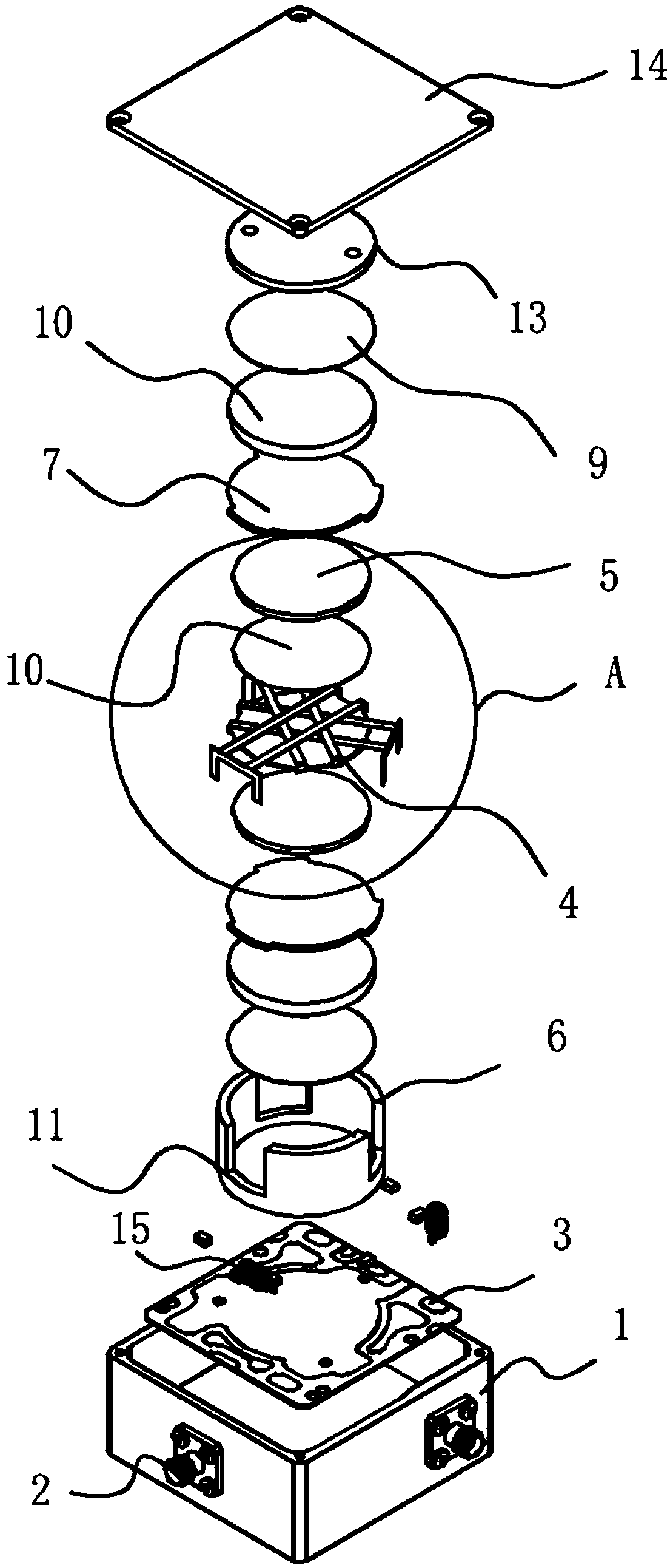
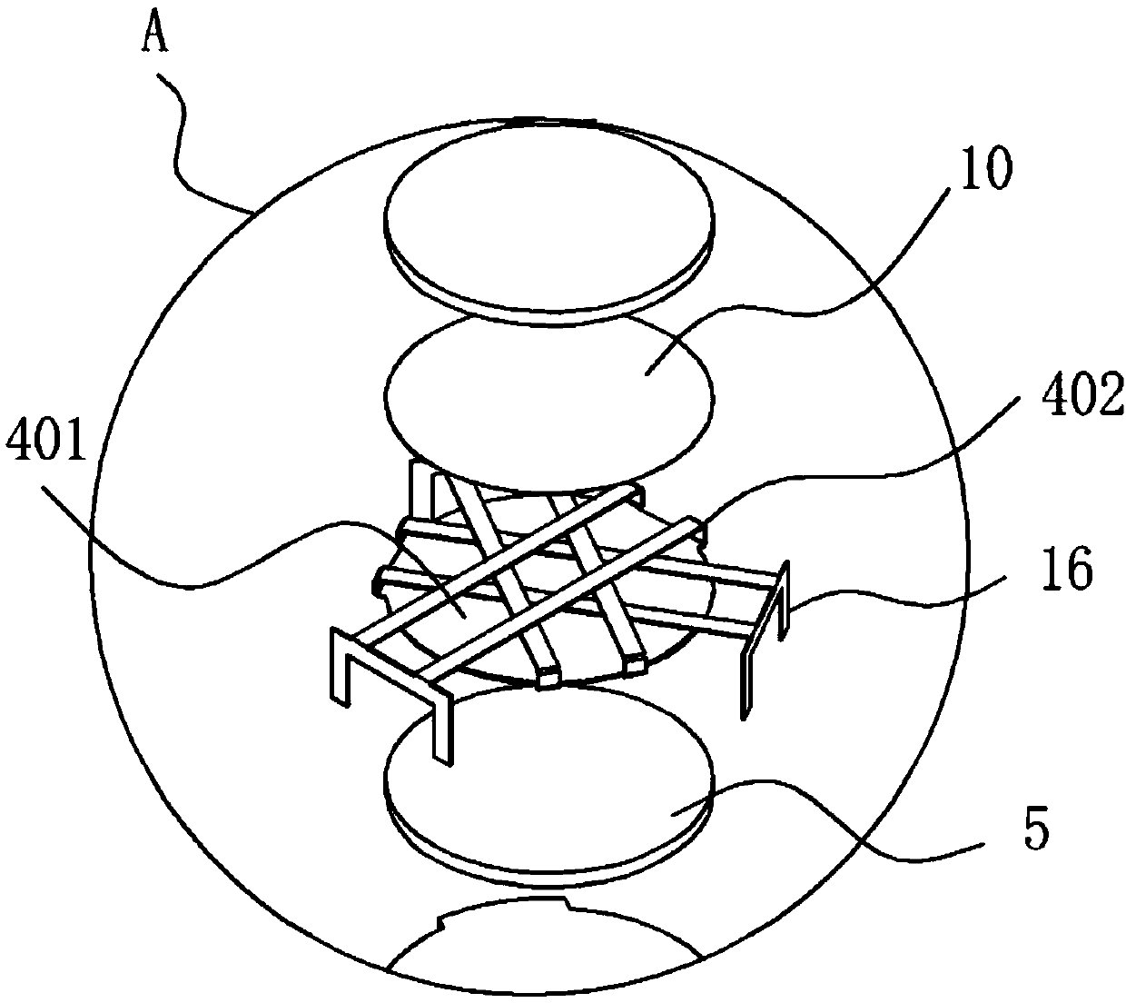
[0029] This embodiment provides a radio frequency communication circulator, such as figure 1 As shown, it includes a casing 1 and an electromagnetic limiting device arranged in the casing 1. The casing 1 is provided with three connectors 2, and the electromagnetic limiting device restricts the one-way circular transmission of signals between the connectors 2; the electromagnetic limiting device includes Circuit board 3 and rotator, described rotator comprises center conductor 4 of Y-shaped structure and is arranged on the ferrite 5 that center conductor 4 is clamped on both sides of center conductor 4, is provided with additional magnetic field outside ferrite 5 to make The ferrite 5 forms a magnet 8 whose gyromagnetic property restricts incoming microwave radio frequency signals to propagate in a one-way ring.
Embodiment 2
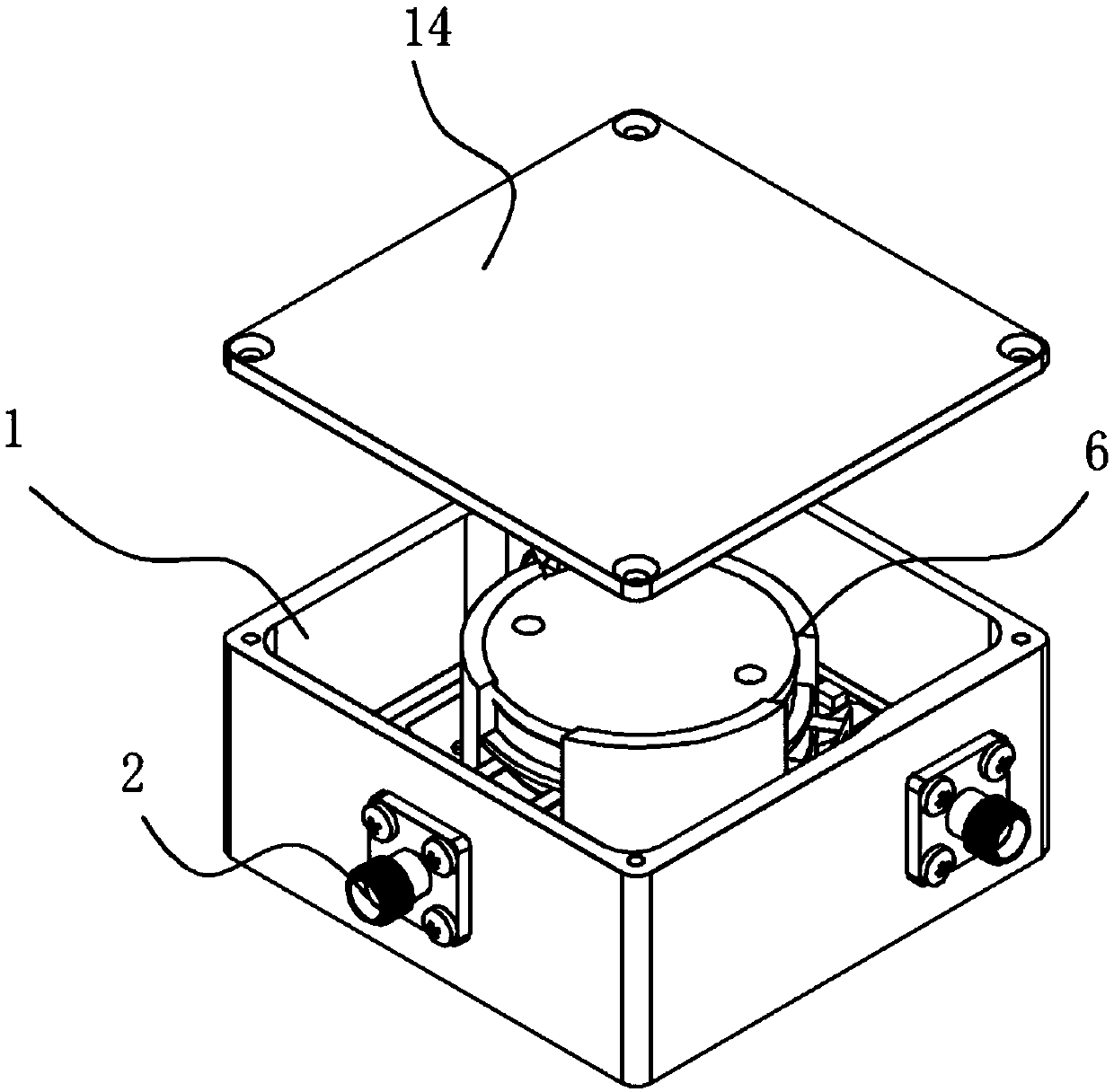
[0031] This embodiment is optimized and defined on the basis of the above-mentioned embodiment 1, such as figure 2 , image 3 , Figure 4 , Figure 5 with Image 6As shown, one side of the housing 1 is provided with an opening and a cover plate 14 for assembly is fitted on the opening. An inner cavity 6 is also provided in the housing 1 , and the central conductor 4 and the ferrite 5 are both arranged in the inner cavity 6 . The inner cavity body 6 is a base structure, and is provided with a cavity for accommodating the gyromagnet, which is convenient for fixing. And three inductance coils 15 corresponding to the connectors 2 are arranged on the circuit board 3 , and a capacitor is provided corresponding to each inductance coil 15 . The electrical signal transmitted through the connector 2 is converted, so that the inductance coil 15 generates a stable magnetic signal. And the printed circuit board 3 selects a high-permittivity high-frequency glass fiber single-sided co...
Embodiment 3
[0033] On the basis of the above-mentioned embodiment 2, further optimization and limitation are carried out. As shown in the figure, thin films 10 are provided on both sides of the central conductor 4, so as to increase the insulating effect. A magnetically conductive sheet 7 for reducing loss is also provided on the outside of the ferrite 5 , and a magnet 8 is arranged on the outside of the magnetically conductive sheet 7 . A compensation sheet 9 is provided outside the magnet 8 .
[0034] That is to say, both sides of the central conductor 4 are film 10, ferrite 5, magnetically conductive sheet 7, magnet 8 and compensating sheet 9 from the inside to the outside, and the rotating magnet is pressed with the compensating sheet 9 on either side as the bottom. Into the inner cavity 6 and at the opening of the inner cavity 6 is provided with a screw cap 13 pressed inward to form the whole inner cavity. The rotary cover 13 can block all parts of the gyromagnetic body in the inner...
PUM
 Abstract
Description
Claims
Application Information
 - R&D
- Intellectual Property
- Life Sciences
- Materials
- Tech Scout
- Unparalleled Data Quality
- Higher Quality Content
- 60% Fewer Hallucinations
Browse by: Latest US Patents, China's latest patents, Technical Efficacy Thesaurus, Application Domain, Technology Topic, Popular Technical Reports.
© 2025 PatSnap. All rights reserved.Legal|Privacy policy|Modern Slavery Act Transparency Statement|Sitemap|About US| Contact US: help@patsnap.com


