High-gain and wide-duty cycle control Boost converter
A converter and duty ratio technology, applied in the field of power electronic converters, can solve the problems of narrow application range and increased circuit control cost, etc., achieve flexible voltage gain adjustment, improve efficiency, and achieve simple effects
- Summary
- Abstract
- Description
- Claims
- Application Information
AI Technical Summary
Problems solved by technology
Method used
Image

Examples
Embodiment 1
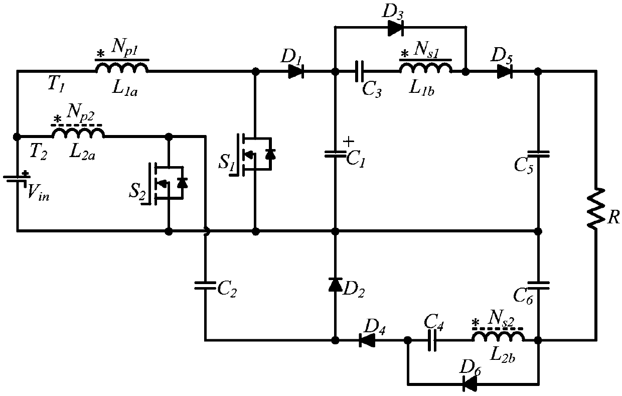
[0054] Such as figure 1 As shown, a high gain, wide duty cycle control Boost converter of this embodiment, the power supply V in The positive poles of the coupled inductors T 1 The primary winding inductance L 1a Terminal of the same name, coupled inductor T 2 The primary winding inductance L 2a terminal connection of the same name, the coupled inductor T 1 The primary winding inductance L 1a The non-identical ends of the switches are respectively connected with the switch tube S 1 Drain, diode D 1 The anode connection of the switching tube S 1 source and supply V in The cathode connection of the diode D 1 The cathode and capacitance C 1 、C 3 one end of the diode D 3 the anode connection, the capacitor C 1 The other end of the power supply V in The negative connection of the capacitor C 3 The other end of the coupled inductor T 1 The secondary winding inductance L 1b Connected to the dotted end, the coupled inductor T 1 The secondary winding inductance L 1b ...
Embodiment 2
[0057] Embodiment 2 Equivalent circuit structure
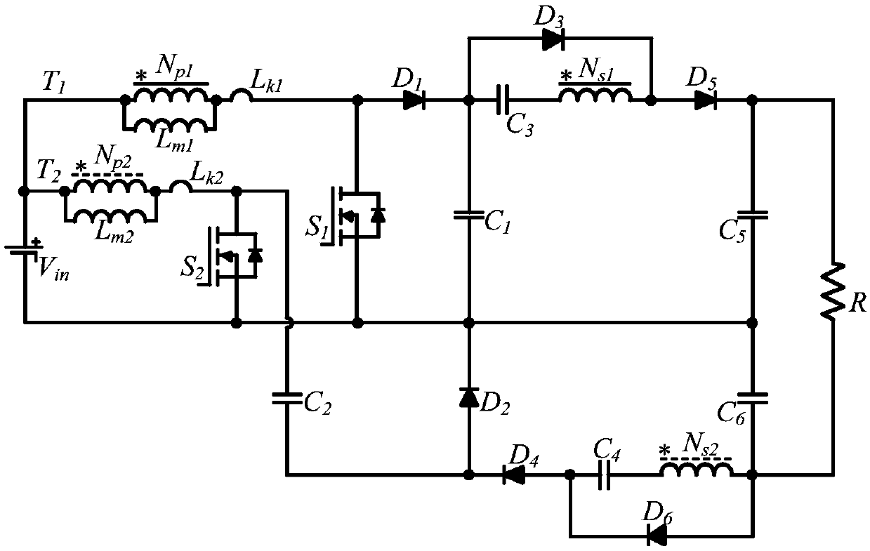
[0058] A high-gain, wide-duty ratio control Boost converter of this embodiment has the same structure as that of Embodiment 1, and its equivalent circuit structure is as follows figure 2 shown.
[0059] figure 2 A kind of high gain, the equivalent structure of wide duty cycle control Boost converter proposed for the present embodiment; Total T in this structure 1 , T 2 Two coupled inductors, combined with figure 1 , each coupled inductor has two windings, and the coupled inductor T 1 and T 2 The end of the same name is represented by "*". Among them, L 1a , L 2a are coupled inductance T 1 , T 2 Primary winding inductance, L 1b , L 2b are coupled inductance T 1 , T 2 Secondary winding inductance, L 1a , L 2a The number of turns are N P1 , N P2 , L 1b , L 2b The number of turns are N s1 , N s2 , coupled inductance T 1 , T 2 The turns ratio is n 1 =N p1 / N s1 , n 2 =N p2 / N s2 . combine figure 2...
Embodiment 3
[0060] Working principle of embodiment 3 (d≥0.5)
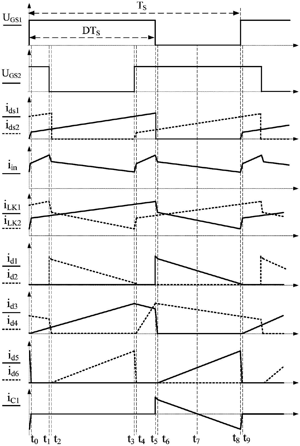
[0061] A kind of high gain, wide duty ratio control Boost converter in the present embodiment, switching tube S 1 and switch tube S 2 The input signal duty ratio of the gate is d≥0.5, and the main working waveform of the converter in this embodiment when d≥0.5 is as follows image 3 As shown, there are 9 working modes in one switching cycle, such as Figure 4-12 shown.
[0062] Modal 1[t 0 -t 1 ]
[0063] at t 0 moment, the switching tube S 1 start conduction, S 2 To maintain conduction, the diode D 1 、D 2 、D 5 and D 6 off, D 3 and D 4 conduction. The corresponding equivalent circuit is as Figure 4 shown, the coupled inductor T 1 The magnetizing inductance L m1 and leakage inductance L k1 In the charging state, the leakage inductance current i Lk1 Gradually increases, the power supply through the secondary winding N of the coupled inductor s1 To the doubler capacitor C 3 Charge. Coupled inductance T 2 ...
PUM
 Abstract
Description
Claims
Application Information
 - R&D
- Intellectual Property
- Life Sciences
- Materials
- Tech Scout
- Unparalleled Data Quality
- Higher Quality Content
- 60% Fewer Hallucinations
Browse by: Latest US Patents, China's latest patents, Technical Efficacy Thesaurus, Application Domain, Technology Topic, Popular Technical Reports.
© 2025 PatSnap. All rights reserved.Legal|Privacy policy|Modern Slavery Act Transparency Statement|Sitemap|About US| Contact US: help@patsnap.com