

Rainwater bio-retention pond structure with submerging layers and method for constructing rainwater bio-retention pond structure
A technology of bioretention ponds and retention ponds, applied to the structure and construction of rainwater bioretention ponds with submerged layers, can solve the problems of poor pollutant treatment effect, difficult plant growth, and inability to store water sources, etc., to achieve enhanced physical Treatment capacity, increasing nitrification and denitrification, and improving the effect of nitrogen and phosphorus removal
- Summary
- Abstract
- Description
- Claims
- Application Information
AI Technical Summary
Problems solved by technology
Method used
Image

Examples
Embodiment 1
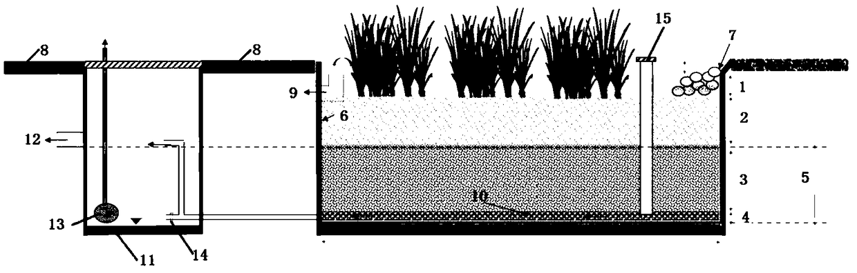
[0068] Beside a city road, build a 5m 2 The small bioretention tank is used to filter and purify the rainwater runoff from the roads on both sides, and then discharge it to the rainwater pipe after purification. Among them: the overall height of the detention tank is 1m, the height of the retention layer 1 is 200mm, the height of the filter layer is 400mm, the height of the transition layer is 300mm, the height of the drainage layer is 100mm, the maximum permeation rate does not exceed 360mm / hr, and the chemical substance content and particle size distribution properties are uniform. Meet the required parameters; among them, add 3kg of organic fertilizer to the 0-100mm filler of the filter layer for plant growth and survival; add 70kg of activated carbon and zero-valent iron mixture to the filter layer; add 36kg of composite microbial embedded particle filler to the transition layer. After the facility is in stable operation, test and analyze the main pollutants in the rainwat...
Embodiment 2
[0072] Build 300m in a park 2 Large-scale bioretention ponds purify the rainwater runoff collected from surrounding green spaces, roads, and parking lots, and at the same time, the influent water mixes with some overflow runoff from surrounding communities, and is discharged into the river after purification. Among them: the overall height of the detention tank is 1.35m, the height of the retention layer 1 is 250mm, the height of the filter layer is 600mm, the height of the transition layer is 300mm, the height of the drainage layer is 200mm, the maximum permeation rate does not exceed 500mm / hr, the chemical substance content and particle size distribution properties All meet the required parameters set forth in the article, among which, 100kg of organic fertilizer is evenly added to the 0-100mm filler of the filter layer; 1000kg of a mixture of zeolite and zero-valent iron is added to the filter layer; 100kg of composite microbial embedded particle filler is added to the trans...
Embodiment 3
[0076] In a large parking lot, build a 20m 2The purified bioretention pond is used to purify the runoff collected from the parking lot and discharge it into the landscape pool after purification. Among them: the overall height of the detention tank is 1.2m, the height of the retention layer 1 is 300mm, the height of the filter layer is 500mm, the height of the transition layer is 300mm, the height of the drainage layer is 100mm, the maximum penetration rate is not more than 500mm / hr, the chemical substance content and particle size distribution properties All meet the required parameters in the article, in which 12kg of organic fertilizer is added to the 0-100mm filler; 200kg of a mixture of activated carbon and zero-valent iron is added to the filter layer; 100kg of composite microbial-embedded granular filler is added to the transition layer. After the facility is in stable operation, test and analyze the main pollutants in the rainwater runoff before and after purification ...
PUM
 Abstract
Description
Claims
Application Information