
A preparation method of rgo/mn/tnts photoelectrode with improved photogenerated charge separation and carbon dioxide reduction performance

A carbon dioxide and photo-generated charge technology, applied in electrodes, electrolysis components, electrolysis process, etc., can solve the problems of low utilization rate of visible light, poor separation of photo-generated charges, etc., and achieve the effects of improved photoelectric performance, improved reduction performance, and good stability.

Active Publication Date: 2019-10-22
HARBIN INST OF TECH
View PDF1 Cites 0 Cited by
  • Summary
  • Abstract
  • Description
  • Claims
  • Application Information

AI Technical Summary

Problems solved by technology

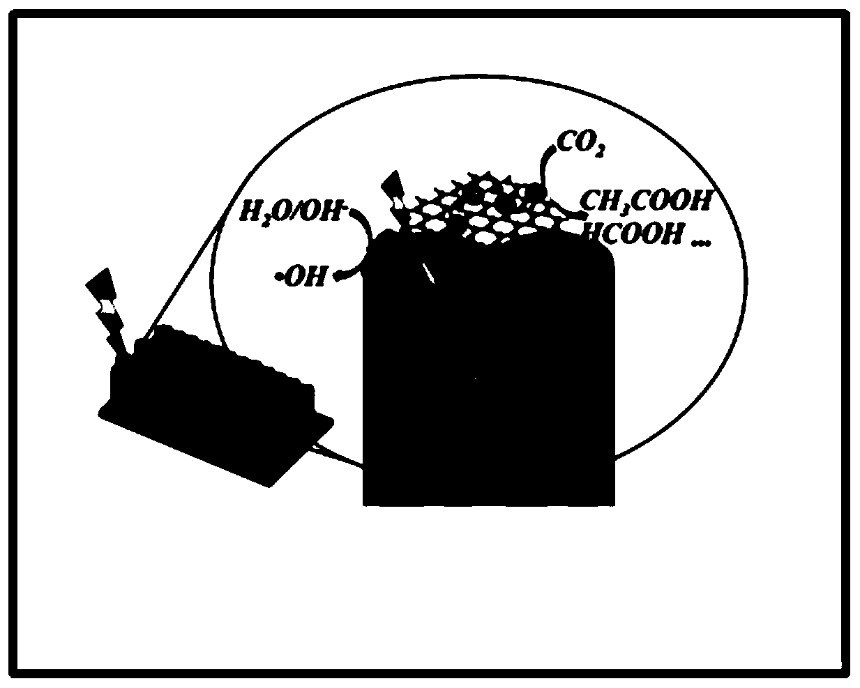
[0006] The present invention will solve existing TiO 2 Photocatalytic reduction of CO by nanotube array photoelectrode 2 In order to solve the technical problems of low utilization rate of visible light and poor separation of photogenerated charges in the process, a preparation method of RGO / Mn / TNTs photoelectrode with improved photogenerated charge separation and carbon dioxide reduction performance is provided

Method used


Image

  • A preparation method of rgo/mn/tnts photoelectrode with improved photogenerated charge separation and carbon dioxide reduction performance
  • A preparation method of rgo/mn/tnts photoelectrode with improved photogenerated charge separation and carbon dioxide reduction performance
  • A preparation method of rgo/mn/tnts photoelectrode with improved photogenerated charge separation and carbon dioxide reduction performance

Examples


specific Embodiment approach 1

[0022] Specific Embodiment 1: In this embodiment, a method for preparing an RGO / Mn / TNTs photoelectrode that improves the separation of photogenerated charges and the reduction performance of carbon dioxide is carried out according to the following steps:

[0023] 1. The pretreated metal Ti foil is used as the anode, the Pt sheet is used as the cathode, and the glycerol solution of ammonium fluoride is used as the electrolyte solution, and the metal Ti foil is treated by anodic oxidation method, and the anodic oxidation voltage is controlled at 5-20V. The oxidation time is 1-5h, take out the metal Ti foil, wash it with deionized water, dry it, put it into a muffle furnace, control the temperature at 100-800°C, and calcinate it for 2-10h to get TiO 2 nanotube arrays;

[0024] 2. Add acetic acid to KMnO 4 solution, magnetically stirred for 5 to 100 minutes, and then added the TiO obtained in step 1 2 The nanotube array is then immersed in a vacuum drying oven for 1 to 10 hours,...

specific Embodiment approach 2

[0026] Embodiment 2: The difference between this embodiment and Embodiment 1 is that in step 1, oxalic acid is used to pretreat the metal Ti foil. Others are the same as in the first embodiment.

specific Embodiment approach 3

[0027] Embodiment 3: The difference between this embodiment and Embodiment 1 or 2 is that the mass concentration of ammonium fluoride in the glycerol solution of ammonium fluoride in step 1 is 0.5%. Others are the same as in the first or second embodiment.


PUM


Abstract

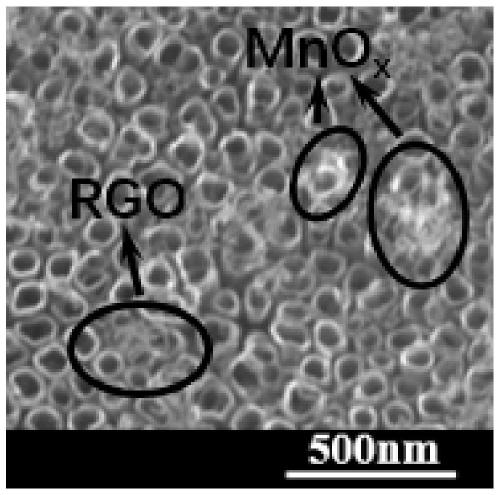
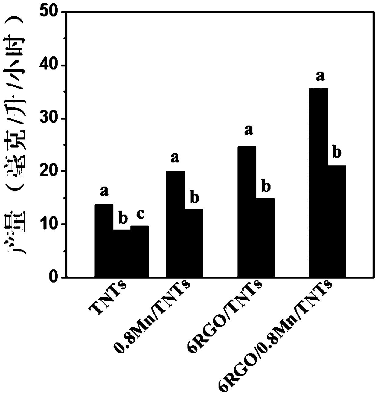
A method for preparing an RGO / Mn / TNTs photoelectrode that improves photogenerated charge separation and carbon dioxide reduction performance, and the invention relates to a method for reducing CO with improved photogenerated charge separation 2 The field of photoelectrode preparation methods. The present invention will solve existing TiO 2 Photocatalytic reduction of CO by nanotube array photoelectrode 2 The technical problems of low utilization rate of visible light and poor separation of photogenerated charges exist in the process. Method: 1. MnOx modified TiO 2 Preparation of nanotube array photoelectrodes; 2. RGO and MnOx co-modified TiO 2 Fabrication of Nanotube Array Photoelectrodes. The invention realizes TiO co-modified by RGO and MnOx 2 Nanotube array photoelectrode for photocatalytic reduction of CO 2 The process of placing the prepared photoelectrode in KHCO containing 0.05M~5M 3 Electrolyte solution, length 4cm, width 3cm, in a plexiglass reactor with quartz glass on one side, extract a certain amount of liquid after irradiating for 1 hour to measure the reduction products therein. The present invention is used to prepare reduced CO modified by RGO and MnOx 2 TiO 2 Nanotube array photoelectrode.

Description

technical field [0001] The present invention relates to improved separation of photogenerated charges for the reduction of CO 2 The field of photoelectrode preparation methods. Background technique [0002] The rapid development of modern society has brought serious environmental pollution and energy problems. The burning of large amounts of fossil fuels makes the CO in the air 2 The rapid growth of carbon dioxide content has caused serious damage to the original carbon cycle balance in nature, resulting in a serious greenhouse effect. How to reduce CO in the air 2 Concentration, effective use of CO 2 , building an environment-friendly, energy-saving low-carbon economy has become a hot spot of extensive research at home and abroad. At the same time, CO 2 As a resource, from the perspective of economy and environmental protection, if it can be converted into organic matter and utilized, it can reduce CO 2 Concentration, while solving environmental problems, a reusable ...

Claims


Application Information

Patent Timeline
Patent Type & Authority Patents(China)
IPC IPC(8): C25B11/06C25B1/00C25B3/04C25D11/26C23C18/12C25D9/08C25B3/25
CPCC23C18/1216C25D9/08C25D11/26C25B3/25C25B1/55C25B11/091
Inventor 冯玉杰吴晶刘佳
Owner HARBIN INST OF TECH
Learn More