Method for preventing pipeline hydrogen damage, and oil transfer line and manifold of oil refining and hydrogen production reformer applying method

A technology of manifolds and oil transfer lines, which is applied in the direction of preventing damage/wear of pipelines, pipeline protection, pipes/pipe joints/fittings, etc. The effect of fatigue tendency and standing wave hazards, long service life and not easy to crack

Inactive Publication Date: 2018-10-26
徐桂根
View PDF0 Cites 2 Cited by
  • Summary
  • Abstract
  • Description
  • Claims
  • Application Information

AI Technical Summary

Problems solved by technology

[0003] The purpose of the present invention is to solve the defects of easy cracking and short service life of the oil transfer line and the manifold used in the hydrogen production reformer, and provide a method for preventing hydrogen damage to the pipeline and the oil refinery hydrogen production reformer transfer line using the method And the collection pipe, after using the present invention, the hydrogen damage of the pipeline is small, not easy to crack, safe, and has a long service life

Method used


Image

  • Method for preventing pipeline hydrogen damage, and oil transfer line and manifold of oil refining and hydrogen production reformer applying method
  • Method for preventing pipeline hydrogen damage, and oil transfer line and manifold of oil refining and hydrogen production reformer applying method
  • Method for preventing pipeline hydrogen damage, and oil transfer line and manifold of oil refining and hydrogen production reformer applying method

Examples


Embodiment 1

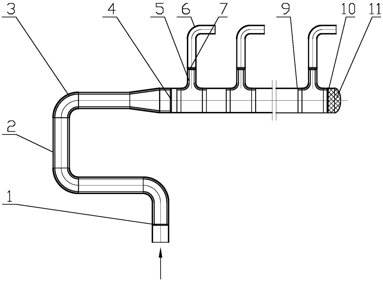
[0037] like figure 1 As shown: the inner wall of the U-shaped oil transfer line 2 is provided with a hollow isolation layer 3, the inlet end and the outlet end are respectively provided with an orifice plate 1 and an orifice plate 4, and the end of the collecting pipe 9 is provided with an orifice plate 10 and a packing 11, A plurality of branch pipes 6 are connected to the side of the collecting pipe 9, the lower part of the branch pipes 6 and the inner wall of the connection between the branch pipes 6 and the collecting pipe 9 are provided with a hollow isolation layer 5, and the branch pipes 6 are provided with orifice plates 7.

[0038] The isolation layer 3 and the isolation layer 5 of this embodiment are hollow liners or bushings, which can effectively reduce the damage of hydrogen to the pipeline. 3. The function of the isolation layer 5 and the filler 11 does not affect the flow of the material at the same time. The filler 11 acts as a buffer, which can effectively red...

Embodiment 2

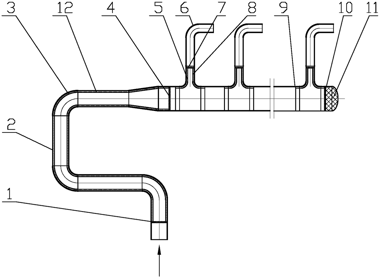
[0040] like figure 2 As shown: the isolation layer 3 and the isolation layer 5 are respectively provided with a filler 12 and a filler 8, and the others are the same as in the first embodiment.

[0041] Compared with Example 1, this embodiment adds filler 12 and filler 8, and the isolation effect is better.

Embodiment 3

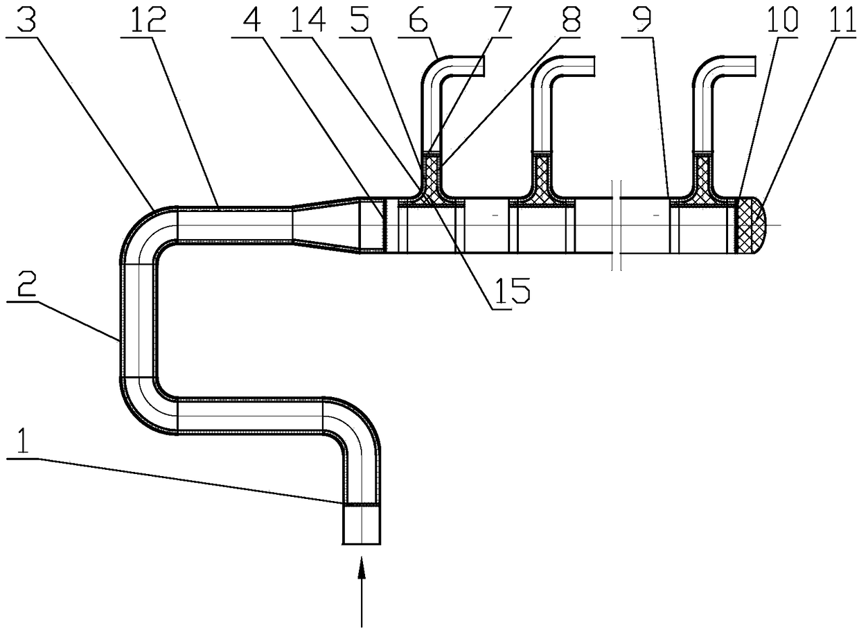
[0043] like image 3 Shown: the inside of the pipeline at the isolation layer 5 is provided with a filler 15, in order to fix the filler 15, an orifice 14 is arranged below it, and the others are the same as in embodiment 2

[0044] Compared with Embodiment 2, this embodiment adds fillers 15 to better protect the branch pipe 6 and the connection between the branch pipe 6 and the manifold 9 .


PUM


Abstract

The invention relates to a method for preventing pipeline hydrogen damage, and an oil transfer line and a manifold of an oil refining and hydrogen production reformer applying the method. The method is characterized in that a hollow isolation layer playing a role in isolating is arranged on the inner wall of a pipeline, padding having a buffer effect is arranged at the tail end of the pipeline, and a pore plate supporting the isolation layer is arranged in the pipeline. The oil transfer line and the manifold of the oil refining and hydrogen production reformer applying the method comprises theoil transfer line and the manifold, and the side face of the manifold is connected with branch pipes. The oil transfer line and the manifold are characterized in that the hollow isolation layer is arranged on the inner wall of the pipeline of the oil transfer line, the padding is arranged at the tail end of the manifold, and hollow isolation layers are arranged on the inner wall of the branch pipes and the inner walls of the connecting portions of the branch pipes and the manifold. The method is not only suitable for the oil transfer line and the manifold of the oil refining and hydrogen production reformer, but also suitable for pigtail tubes, propylene dehydrogenation tubes, isobutene dehydrogenation tubes, and other chemical device pipelines having hydrogen damage problems. Pipelines applying the method have the advantages of being long in service life and not liable to cracking.

Description

technical field [0001] The invention specifically relates to a method for preventing hydrogen damage to pipelines and a conversion line and collecting pipe of a reformer for oil refining and hydrogen production using the method. Background technique [0002] The reformer for hydrogen production uses natural gas, oil field gas, coke oven gas, refinery tail gas or light oil as raw materials under high temperature and high pressure conditions, and with the help of the nickel-based catalyst in the reformer tube, the raw material and water vapor are generated in the reformer. High-temperature equipment for producing hydrogen by conversion reaction inside the tube. Oil transfer lines, manifolds, and pigtail pipes are the matching pipelines. After the hydrogen production reformer has been used for a period of time, the above-mentioned pipelines often crack and have a short service life. The fire caused huge economic losses. Contents of the invention [0003] The purpose of the ...

Claims


Application Information

Patent Timeline
Patent Type & Authority Applications(China)
IPC IPC(8): F16L43/00F16L41/03F16L57/02F16L55/027F16L55/04
CPCF16L41/03F16L43/00F16L55/02718F16L55/04F16L57/02
Inventor 徐桂根
Owner 徐桂根
Why Eureka
Try Eureka