
Vacuumizing, liquid filling and sealing device and method for plate multi-channel heat pipe

A flat heat pipe and sealing device technology, applied in indirect heat exchangers, lighting and heating equipment, etc., can solve the problems of high cost and low efficiency, and achieve the effects of precise liquid injection, low energy consumption and simple structure

Pending Publication Date: 2018-10-26
SOUTH CHINA UNIV OF TECH +1
View PDF1 Cites 3 Cited by
  • Summary
  • Abstract
  • Description
  • Claims
  • Application Information

AI Technical Summary

Problems solved by technology

The method of using a single syringe to inject liquid into the channel multiple times is inefficient, while the simultaneous injection of multiple channels using multiple syringes is costly, so it is of great significance to design a device and method with high efficiency and low cost

Method used


Image

  • Vacuumizing, liquid filling and sealing device and method for plate multi-channel heat pipe
  • Vacuumizing, liquid filling and sealing device and method for plate multi-channel heat pipe
  • Vacuumizing, liquid filling and sealing device and method for plate multi-channel heat pipe

Examples


Embodiment 1

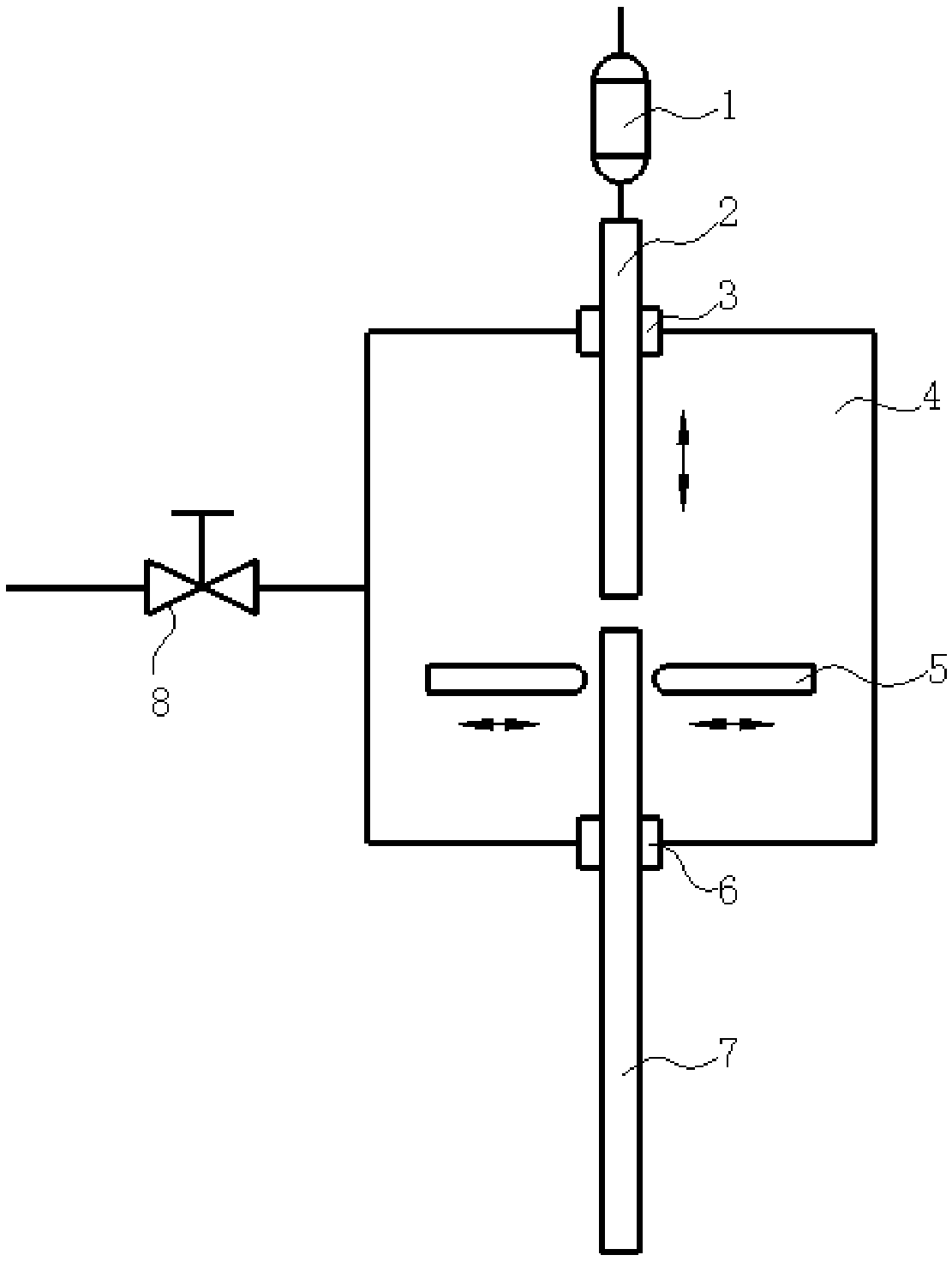
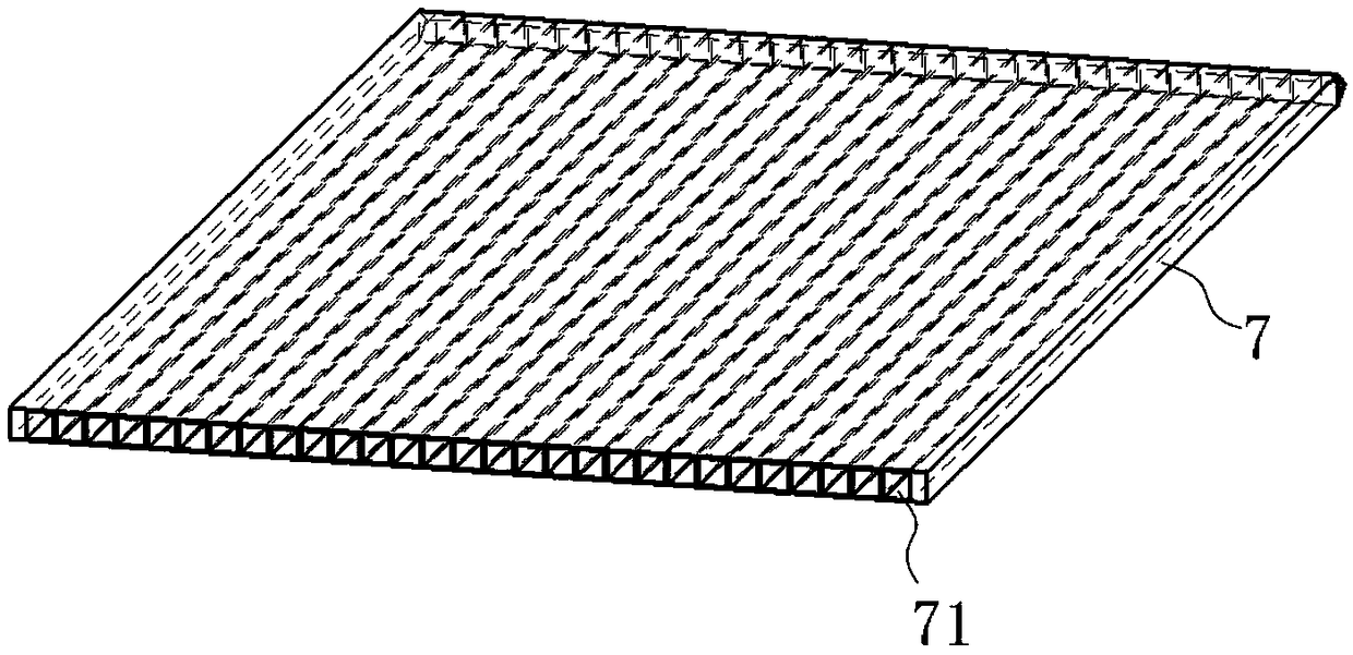
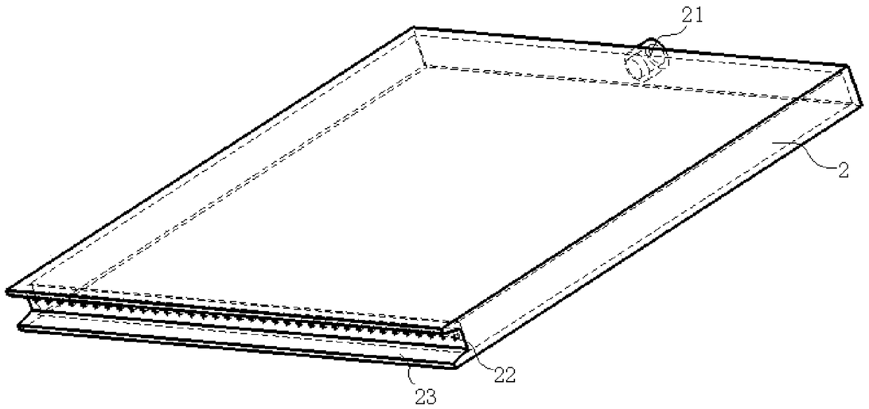
[0035] like figure 1 As shown, a vacuum injection liquid sealing device for a flat multi-channel heat pipe includes a vacuum cavity 4 connected to a vacuum valve 8, a quantitative liquid injection pump 1, a liquid injection plate 2, and a sealing mold 5. In this embodiment, as figure 2 As shown, a plurality of channels 71 are arranged inside the flat heat pipe 7 , each channel 71 is not connected to each other, one end is sealed by welding, and the other end is opened for vacuuming and liquid injection. like image 3 As shown, the liquid injection plate 2 is provided with a cavity, one end of which is provided with a liquid inlet 21 connected to the quantitative liquid injection pump 1, and the other end is provided with a number of passages 71 with the same number and positions as the flat heat pipe 7. Corresponding to the liquid injection hole 22, the liquid inlet 21 is connected to the quantitative liquid injection pump 1 through a pipeline, and one end provided with the ...

Embodiment 2

[0039] A method for vacuumizing liquid injection and sealing by using the device as described, comprising the steps of:

[0040] 1) Insert the flat heat pipe 7 vertically into the vacuum chamber 4 from the lower end through the sealed socket and control the distance between the upper end of the flat heat pipe 7 and each liquid injection hole 22 to be 0.5-5mm, so that each liquid injection hole 22 One-to-one correspondence with each channel 71 of the flat heat pipe 7;

[0041] 2) The vacuum valve 8 is opened to communicate with the vacuum pump and the vacuum chamber 4, and the vacuum valve 8 is closed after becoming a vacuum state in the vacuum chamber 4 to disconnect the vacuum pump and the vacuum chamber 4;

[0042] 3) Start the quantitative injection pump 1 to inject a quantitative working medium, the working medium is acetone or ammonia water, the working medium passes through the liquid inlet 21, and then passes through a plurality of liquid injection holes 22 to evenly di...

Embodiment 3

[0047] A method for vacuumizing liquid injection and sealing by using the device as described, comprising the steps of:

[0048] 1) Insert the flat heat pipe 7 vertically from the lower end into the vacuum chamber 4 through the sealed socket;

[0049] 2) The vacuum valve 8 is opened to communicate with the vacuum pump and the vacuum chamber 4, and the vacuum valve 8 is closed after becoming a vacuum state in the vacuum chamber 4 to disconnect the vacuum pump and the vacuum chamber 4;

[0050] 3) The liquid injection plate 2 is moved down close to the flat heat pipe 7, so that each liquid injection hole 22 corresponds to each channel 71 of the flat heat pipe 7;

[0051] 4) Start the quantitative injection pump 1 to inject a quantitative working medium, the working medium is acetone or ammonia water, the working medium passes through the liquid inlet 21, and then passes through a plurality of liquid injection holes 22 to evenly distribute the working medium into each channel 71 ...


PUM

PropertyMeasurementUnit
Diameteraaaaaaaaaa

Abstract

The invention discloses a vacuumizing, liquid filling and sealing device for a plate multi-channel heat pipe. The vacuumizing, liquid filling and sealing device comprises a vacuum cavity connected with a vacuum valve, a quantitative liquid filling pump, a liquid filling plate and sealing molds; a cavity is formed in the liquid filling plate, one end of the liquid filling plate is provided with a liquid inlet connected with the quantitative liquid filling pump, and the other end of the liquid filling plate is provided with a plurality of liquid filling holes of which the number is the same as that of channels of the plate heat pipe and the positions correspond to those of the channels of the plate heat pipe one to one; the liquid inlet is connected with the quantitative liquid filling pumpthrough a pipeline, and the end with the liquid filling holes vertically stretches into the vacuum cavity from the upper end of the vacuum cavity in a sealing and matching mode; and sealing ports usedfor allowing the plate heat pipe to be filled with liquid to stretch into the vacuum cavity in a sealing and matching mode are oppositely arranged at the lower end of the vacuum cavity, and the sealing molds are arranged in the vacuum cavity and located on the two sides of the plate heat pipe. The invention further discloses a vacuumizing, liquid filling and sealing method for the plate multi-channel heat pipe. According to the vacuumizing, liquid filling and sealing device and method for the plate multi-channel heat pipe, the efficiency is high, the cost is low, the filling amount of all thechannels is same and precise, and the vacuumizing, liquid filling and sealing device and method are suitable for filling volatile and toxic working media.

Description

technical field [0001] The invention relates to a heat pipe vacuum injection liquid sealing process, in particular to a vacuum liquid injection sealing device and method for flat multi-channel heat pipes, which can realize vacuuming, precise and uniform liquid injection and sealing of multi-channel heat pipes. Background technique [0002] The sequestration capacity of each channel of a multi-channel heat pipe is a key factor affecting the performance of the heat pipe, so it is particularly important to ensure accurate and uniform liquid injection in each channel. The method of using a single syringe to inject liquid into the channels multiple times is inefficient, while the simultaneous injection of multiple channels using multiple syringes is costly. Therefore, it is of great significance to design a device and method with high efficiency and low cost. [0003] Patent: CN 104006687 A (Notice No.) discloses a working fluid steam injection device and method for a flat multi-...

Claims


Application Information

Patent Timeline
IPC IPC(8): F28D15/02
CPCF28D15/0283
Inventor 黄光文李勇何柏林周文杰陈韩荫陈创新
Owner SOUTH CHINA UNIV OF TECH
Learn More