Self-expansion intervention valve stent for preventing coronary artery from being shielded

A self-expanding, valve technology, applied in stents and other directions, can solve the problems of coronary artery occlusion, coronary insufficiency, etc., to achieve the effect of reducing coverage, reducing contact area, and reducing coronary insufficiency

Inactive Publication Date: 2018-11-02
BEIHANG UNIV
View PDF14 Cites 3 Cited by
  • Summary
  • Abstract
  • Description
  • Claims
  • Application Information

AI Technical Summary

Problems solved by technology

However, because the entrance of the coronary artery is on the aortic sinus, the mesh metal structure of the stent may caus...

Method used


Image

  • Self-expansion intervention valve stent for preventing coronary artery from being shielded
  • Self-expansion intervention valve stent for preventing coronary artery from being shielded

Examples


Embodiment Construction

[0021] The present invention will now be further described in conjunction with the accompanying drawings and specific embodiments.

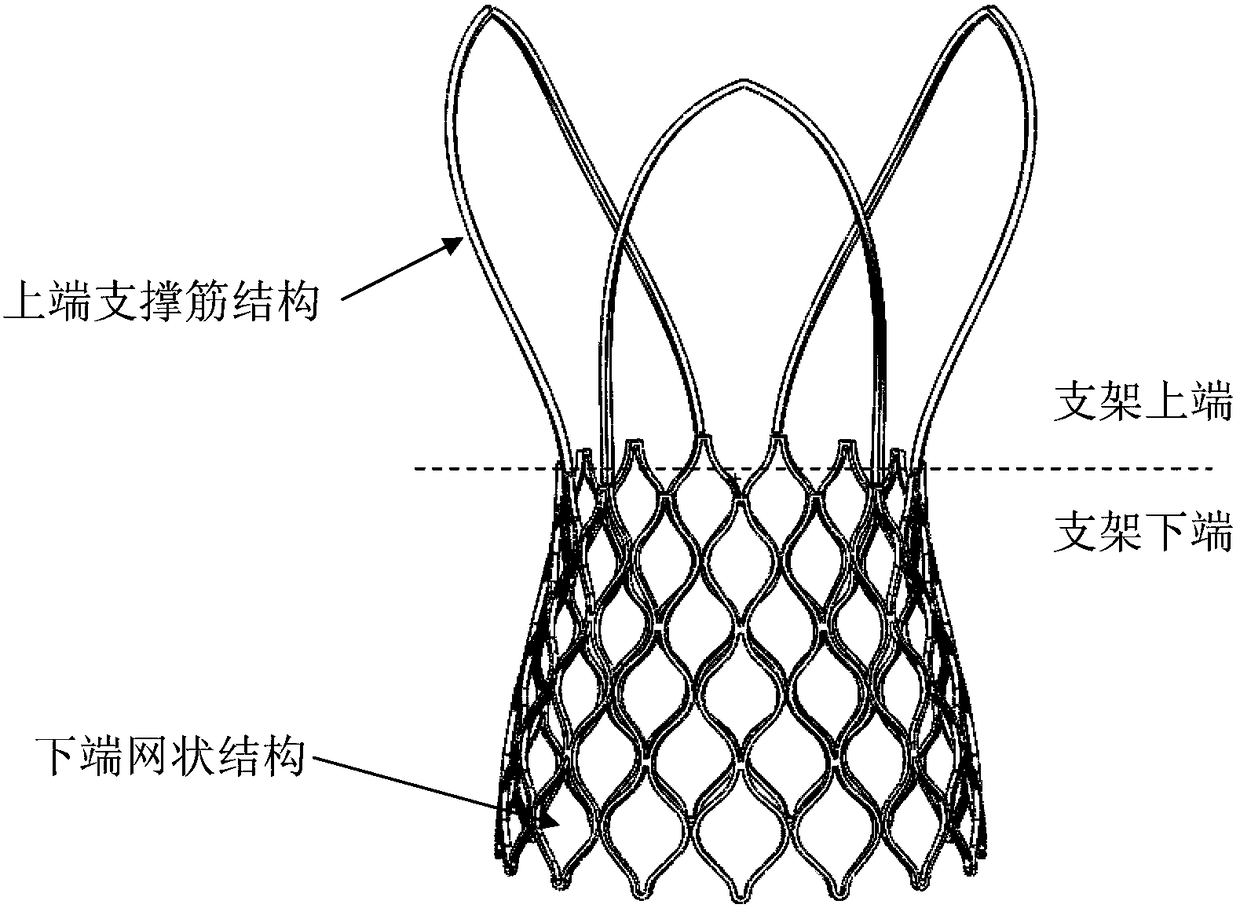
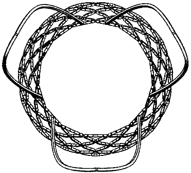
[0022] According to an embodiment of the present invention, a self-expanding interventional valve stent capable of avoiding coronary artery occlusion is made of a memory alloy with good biocompatibility, such as nickel-titanium alloy. Such as figure 1 As shown, the bracket includes two parts, the upper end and the lower end. The two parts are directly connected. The whole bracket is in the shape of a dumbbell, the diameter of the middle part is the smallest, and the upper and lower ends expand, and the diameter of the upper end is slightly larger than or the same as that of the lower end.

[0023] The lower end of the stent is the fixed area of ​​the valve, and the three leaflets (not shown) are sutured on the metal ribs of the mesh structure of the stent by suturing, and the specific suturing position is determined according to the difference ...


PUM


Abstract

The invention discloses a self-expansion intervention valve stent for preventing the coronary artery from being shielded, and relates to the field of intervention therapy equipment for cardiovasculardiseases. The intervention valve stent is composed of two parts including the upper end and the lower end; the upper end is composed of three arc supporting ribs, and the supporting ribs are of an annular structure and expand outwards from bottom to top; the lower end is composed of one circle of 6 or more quadrangular net-shaped structures in the circumferential direction. The cross section areaof the supporting ribs at the upper end is equal to or larger than that of metal ribs of the quadrangular structures at the lower end to provide radial support force with proper intensity. By means ofthe self-expansion intervention valve stent, the metal coverage area of the upper half part of the self-expansion intervention valve stent is reduced, and the coronary artery can be prevented from being shielded by the stent.

Description

technical field [0001] The invention relates to a self-expanding interventional valve support capable of avoiding coronary artery occlusion. Background technique [0002] Interventional prosthetic heart valve implantation is a minimally invasive procedure to treat aortic valve stenosis caused by degenerative diseases. A stented valve is delivered through a catheter to the aortic root to distract and replace the diseased, stenotic native valve. Generally, self-expanding or balloon-expanding methods are used to support the aortic root. [0003] However, the current interventional valves are still not perfect. The self-expanding form of the stent is anchored in the sinus of the aorta by virtue of its enlarged upper diameter structure to form a firm fixation that resists pressure on the aorta. However, since the entrance of the coronary artery is on the aortic sinus, the mesh metal structure of the stent may cause obstruction of the coronary artery, resulting in insufficient ...

Claims


Application Information

Patent Timeline
IPC IPC(8): A61F2/90
CPCA61F2/90
Inventor 樊瑜波冯文韬储照伟郭萌
Owner BEIHANG UNIV
Why Eureka
Try Eureka