Energy-saving and emission-reducing exhaust gas desulfurization tower

A waste gas desulfurization, energy saving and emission reduction technology, which is applied in the direction of gaseous effluent wastewater treatment, water/sludge/sewage treatment, separation devices, etc., can solve the problems of poor desulfurization effect, desulfurization agent spray operation, and poor waste gas treatment effect, etc. problems, to achieve the effect of improving desulfurization efficiency, improving mixing degree, and good use effect

Inactive Publication Date: 2018-11-02
孙菊萍
View PDF0 Cites 16 Cited by
  • Summary
  • Abstract
  • Description
  • Claims
  • Application Information

AI Technical Summary

Problems solved by technology

[0003] However, in traditional desulfurization towers, the desulfurizer spraying devices are generally set to be fixedly connected. The structure of the fixed connection often makes it impossible to spray the desulfurizer in the largest range, and the exhaust gas is introduced into the desulfurizer to be in contact with the desulfurizer. Contact, the exhaust gas cannot be evenly distributed and diffused, resulting in insufficient contact between the exhaust gas and the desulfurizer, resulting in poor desulfurization effect and poor exhaust gas treatment effect

Method used


Image

  • Energy-saving and emission-reducing exhaust gas desulfurization tower
  • Energy-saving and emission-reducing exhaust gas desulfurization tower
  • Energy-saving and emission-reducing exhaust gas desulfurization tower

Examples


Embodiment Construction

[0019] The following will clearly and completely describe the technical solutions in the embodiments of the present invention with reference to the accompanying drawings in the embodiments of the present invention. Obviously, the described embodiments are only some, not all, embodiments of the present invention.

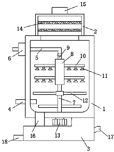
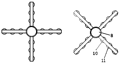
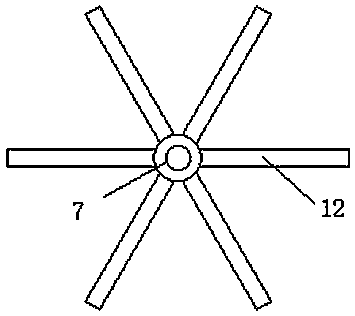
[0020] refer to Figure 1-3 , an energy-saving and emission-reducing waste gas desulfurization tower, comprising a tower body 1, a demister box 2 and a waste liquid treatment tank 3, the demist box 2 is fixedly connected to the upper end of the tower body 1, and the waste liquid treatment tank 3 is fixedly connected to the tower body 1 The lower end of the tower body 1 is provided with an inlet pipe 4 on the side wall near the lower end, the waste gas is discharged into the tower body 1 through the inlet pipe 4, and the side wall of the tower body 1 near the upper end is provided with a liquid inlet pipe 5, and the liquid inlet pipe 5 One end of the tower body 1 runs...


PUM


Abstract

The invention discloses an energy-saving and emission-reducing exhaust gas desulfurization tower. The energy-saving and emission-reducing exhaust gas desulfurization tower comprises a tower body, a demisting tank and a waste liquid treatment tank, wherein the demisting tank is fixedly connected to the upper end of the tower body, the waste liquid treatment tank is fixedly connected to the lower end of the tower body, a gas inlet pipe is arranged on the side wall close to the lower end of the tower body, a liquid inlet pipe is arranged on the side wall close to the upper end of the tower body,one end of the liquid inlet pipe penetrates through the tower body and extends inside the tower body, a spraying device communicated with the liquid inlet pipe is arranged inside the tower body, a gasdispersing mechanism is rotatably connected with the internal bottom of the tower body, the upper end of the gas dispersing mechanism is fixedly connected with the spraying device, the lower end of the tower body is fixedly connected with a rotating motor used for driving the gas dispersing mechanism, and a gas outlet is formed in the upper end of the demisting tank. According to the energy-saving and emission-reducing exhaust gas desulfurization tower, the structure is compact, the thorough mixing between exhaust gases and a desulfurization solution is improved, and thus, the desulfurizationeffect of the exhaust gases is improved; desulfurized waste liquid is further treated, so that the discharge of harmful liquid is avoided.

Description

technical field [0001] The invention relates to the technical field of waste gas desulfurization, in particular to an energy-saving and emission-reducing waste gas desulfurization tower. Background technique [0002] At present, industrial coal is used in the production process of high-energy-consuming and high-pollution industries such as petrochemical, nonferrous metals, and steel. The waste gas discharged after coal combustion contains a large amount of sulfide, and direct discharge will cause serious air pollution. Usually, The exhaust gas needs to be desulfurized. The commonly used desulfurization agent is acid liquid. The industrial waste gas is discharged into the desulfurization tower and sprayed. The sulfide reacts with the acid liquid to form gypsum, so as to realize the treatment of flue gas and reuse the by-products. [0003] However, in traditional desulfurization towers, the desulfurizer spraying devices are generally set in a fixed connection. The structure o...

Claims


Application Information

Patent Timeline
Patent Type & Authority Applications(China)
IPC IPC(8): B01D53/78B01D53/50C02F1/00C02F103/18
CPCB01D53/78B01D53/50B01D2247/10C02F1/00C02F2001/007C02F2103/18
Inventor 倪飞冯翼飞陈太华孙志东倪加邦
Owner 孙菊萍
Why Eureka
Try Eureka