Eureka AIR delivers breakthrough ideas for toughest innovation challenges, trusted by R&D personnel around the world.

Connection joint structure for circular concrete filled steel tubular column and reinforced concrete beam and construction method thereof

A technology for reinforced concrete beams and CFST columns is applied in the connection node structure and construction field of circular CFST columns and reinforced concrete beams, and can solve the difficulties in connecting circular CFST columns and reinforced concrete beams, the connection forms are not rich enough, and the Complex node design and other problems, to achieve the effect of good economic performance, shortened construction period, and fast construction method

Pending Publication Date: 2018-11-02
CHANGAN UNIV
View PDF4 Cites 3 Cited by
  • Summary
  • Abstract
  • Description
  • Claims
  • Application Information

AI Technical Summary

Problems solved by technology

However, at present, it is difficult to connect circular concrete-filled steel pipe columns and reinforced concrete beams, and the connection forms are not rich enough. The previous joint design is relatively complicated, and on-site construction is difficult.

Method used


Image

  • Connection joint structure for circular concrete filled steel tubular column and reinforced concrete beam and construction method thereof
  • Connection joint structure for circular concrete filled steel tubular column and reinforced concrete beam and construction method thereof
  • Connection joint structure for circular concrete filled steel tubular column and reinforced concrete beam and construction method thereof

Examples


Embodiment Construction

[0036] Embodiments of the present invention will be described in detail below in conjunction with examples, but those skilled in the art will understand that the following examples are only used to illustrate the present invention, and should not be considered as limiting the scope of the present invention.

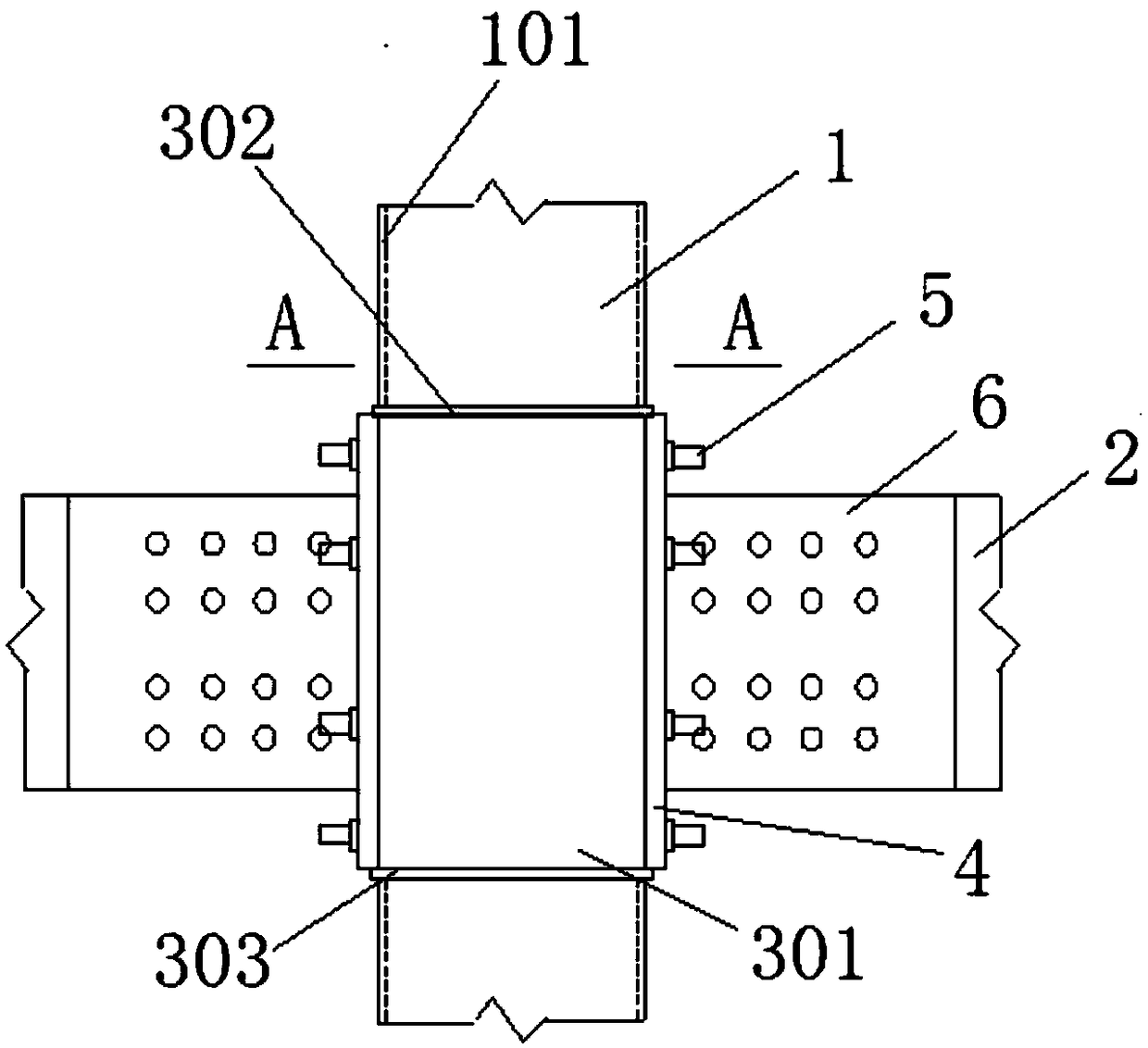
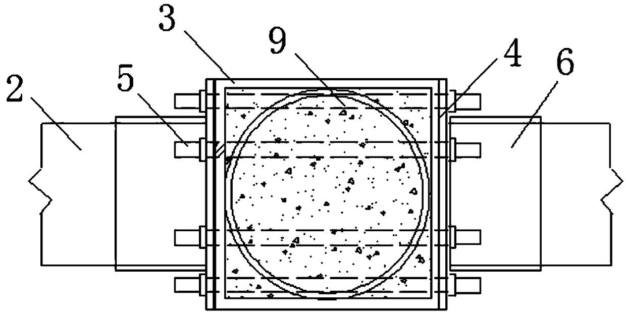
[0037] refer to figure 1 and figure 2 , the embodiment of the present invention provides a connection node structure between a circular steel pipe concrete column 1 and a reinforced concrete beam 2, including: a circular steel pipe 101, a node adapter 3, a stud bolt 5, a steel plate 6 and a reinforced concrete beam 2 The inside of the circular steel pipe 101 is hollow, and concrete is poured inside it to form a circular steel pipe concrete column 1 .

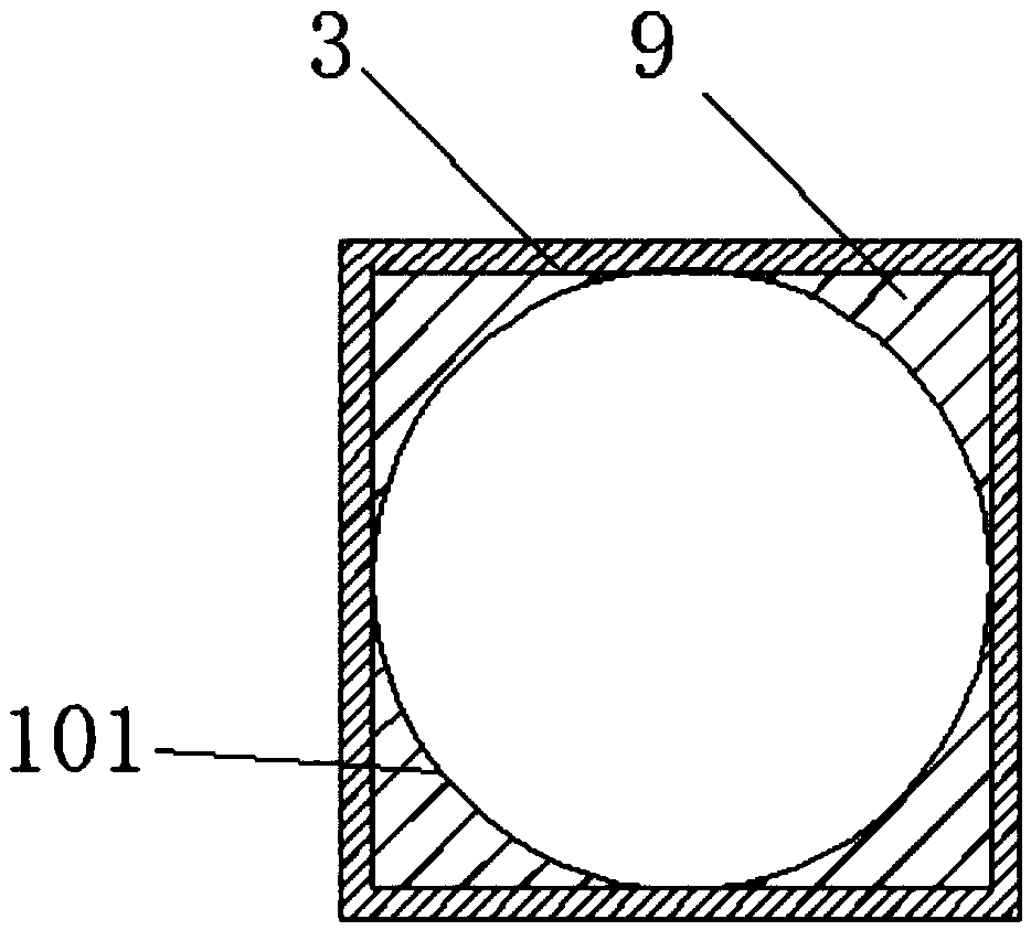
[0038] refer to figure 2 and image 3 , the outer wall of the node adapter 3 is a vertical square steel pipe 301, the vertical square steel pipe 301 is set on the outer wall of the circular steel pipe 101, and the inne...


PUM


Abstract

The invention discloses a connection joint structure for a circular concrete filled steel tubular column and a reinforced concrete beam. The connection joint structure comprises a circular steel tube,a joint adapting part and a reinforced concrete beam. A vertical square steel tube on the outer side wall of the joint adapting part is in sleeve joint with the circular steel tube. The upper end andthe lower end of the vertical square steel tube are respectively equipped with an upper end cover and a lower end cover. Concrete or mortar is poured between the vertical square steel tube and the circular steel tube. The side surface of the vertical square steel tube is equipped with end plates. Multiple double-head bolts respectively and horizontally penetrate through two sides of the circularsteel tube and the vertical square steel tube and stretch out of the end plates. Two sides at the end part of the reinforced concrete beam are equipped with steel plates. The multiple double-head bolts horizontally penetrate through the reinforced concrete beam and steel plates. The steel plates and the end plates are connected in a welding manner. The invention also discloses the construction method thereof for the connection joint structure for the circular concrete filled steel tubular column and the reinforced concrete beam. The connection joint structure is high in carrying capability andsimple in construction. The construction method is quick and simple. The construction period can be evidently shortened. The connection joint structure is highly cost-effective.

Description

technical field [0001] The invention relates to the technical field of construction engineering and combined structures, in particular to a connection node structure and a construction method of a circular steel pipe concrete column and a reinforced concrete beam. Background technique [0002] As a new building structure, the concrete-filled steel tube structure has been widely used in engineering practice due to its remarkable characteristics such as high strength, good seismic performance, and convenient construction. The circular steel pipe has a higher bearing capacity due to its stronger restraint on the internal concrete than the square steel pipe. However, at present, it is difficult to connect circular concrete-filled steel pipe columns and reinforced concrete beams, and the connection forms are not rich enough. The previous joint design is relatively complicated, and on-site construction is difficult. Contents of the invention [0003] Aiming at the problems exis...

Claims


Application Information

Patent Timeline
Patent Type & Authority Applications(China)
IPC IPC(8): E04B1/20E04B1/21E04G21/00
CPCE04B1/20E04B1/215E04G21/00
Inventor 卜永红
Owner CHANGAN UNIV
Why Eureka
Eureka Blog
Learn More