Indoor visible light positioning method based on neural network and received signal intensity

A technology of received signal strength and neural network, applied in the field of indoor visible light positioning, can solve the problems of huge amount of sampled data, insufficient optimization of neural network algorithm for positioning accuracy, and low operation speed

Active Publication Date: 2018-11-02
BEIJING INSTITUTE OF TECHNOLOGYGY
View PDF11 Cites 14 Cited by
  • Summary
  • Abstract
  • Description
  • Claims
  • Application Information

AI Technical Summary

Problems solved by technology

[0003] The purpose of the present invention is to solve the problem that the existing indoor visible light positioning system based on received signal strength has low positioning accuracy, low operation speed, and large amount of sampled data in large scenes due to inherent defects of devices, external environmental influences, and insufficient optimization of neural network algorithms. problem, a method for indoor visible light localization based on neural network and received signal strength is proposed

Method used


Image

  • Indoor visible light positioning method based on neural network and received signal intensity
  • Indoor visible light positioning method based on neural network and received signal intensity
  • Indoor visible light positioning method based on neural network and received signal intensity

Examples


Embodiment 1

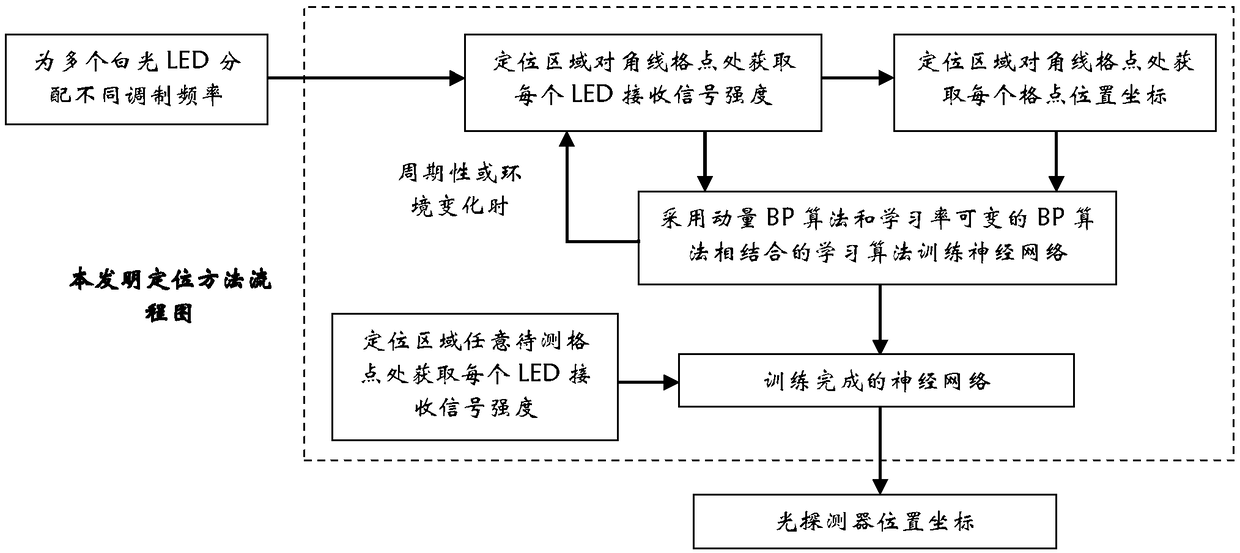
[0086] The present embodiment has described the flowchart of the method of the present invention, as attached figure 1 shown, including the following steps:

[0087] Step A assigns different modulation frequencies to multiple white LEDs;

[0088] Step B: obtain the received signal strength of each LED at the diagonal grid point of the positioning area;

[0089] Step C: Obtain the position coordinates of each grid point at the diagonal grid point of the positioning area;

[0090] Step D adopts the learning algorithm combining the momentum BP algorithm and the variable learning rate BP algorithm to train the neural network to obtain the trained neural network;

[0091] In order to obtain precise positioning effects, the training of the neural network needs to be repeated periodically or when the environment changes;

[0092] Step E: Obtain the received signal strength of each LED at any grid point to be measured in the positioning area, and input the trained neural network in...

Embodiment 2

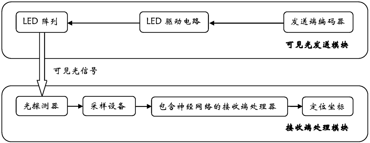
[0095] Embodiment 2 provides a positioning system constructed according to the "Indoor Visible Light Positioning Method Based on Neural Network and Received Signal Strength" of the present invention, as shown in the attached figure 2 shown. The positioning system mainly includes two parts: the visible light sending module and the receiving end processing module;

[0096] The visible light transmission module also includes three parts: the transmitter encoder, the LED drive circuit and the LED array;

[0097] Among them, the encoder at the sending end can be an FPGA or a single-chip microcomputer, and its function is to generate periodic signals of different frequencies sent by the white LEDs of the LED array. The frequency range of the periodic signals is 800Hz-4kHz, and 4 LEDs are used in the LED array;

[0098] Specifically in this embodiment, the encoder at the sending end uses FPGA, and 4 LEDs are used in the LED array, and the frequencies of the periodic signals sent by...

Embodiment 3

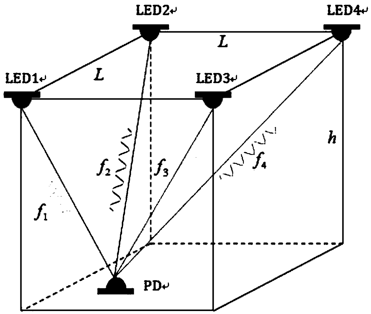
[0110] Embodiment 2 provides a specific scene for indoor positioning according to the "Indoor Visible Light Positioning Method Based on Neural Network and Received Signal Strength" of the present invention, as shown in the attached image 3 shown. The size of the indoor scene is 70cm╳70cm╳100cm, and the positioning area is 60cm╳60cm.

[0111] Specifically in this embodiment, Step 1 is refined as follows: install 4 white LED lights on the ceiling, and use on-off keying (00K) for frequency modulation, the frequency range is 800Hz-4kHz, and the modulation frequency is not a multiple of each other. 885Hz, 1725Hz, 2500Hz and 3125Hz, sending visible light signals vertically downward;

[0112] Specifically in this embodiment, step 2 is refined as follows: place photodiodes horizontally in the positioning area 1 meter below the ceiling; the positioning area is evenly divided into 49 grid points, wherein the distance between adjacent grid points is 10 cm; the neural network The train...


PUM


Abstract

The invention discloses an indoor visible light positioning method based on neural network and received signal intensity, which belongs to the technical field of visible light communication. The diagonal upper grid points of the positioning area are taken as a neural network training set, and different modulation frequencies are distributed for a plurality of white light LEDs. Training is carriedout on the neural network by utilizing the received signal intensity of each LED at the training set position and the actual coordinate value of a light detector. A learning algorithm combines a momentum BP algorithm and a BP algorithm with variable learning rate. The received signal intensity of each LED on any grid point to be measured is input into a trained neural network to obtain the position coordinates of the light detector. The neural network adopts a special training set and an optimized learning algorithm, the sampling data quantity in a large scene can be effectively reduced, and the network training speed and the indoor positioning precision can be improved; the positioning system is not affected by external factors such as multi-path reflection; the system hardware is based on a traditional visible light positioning system, and extra investment is not needed.

Description

technical field [0001] The invention relates to an indoor visible light positioning method based on a neural network and received signal strength, and belongs to the technical field of visible light communication. Background technique [0002] The indoor positioning solution based on visible light communication (Visible Light Communication, VLC) technology has three major advantages: 1) Using semiconductor light-emitting diodes (Light Emitting Diode, LED) to emit positioning signals, the price is low, the energy efficiency is high, and the service life is long, and it is widely used in Indoor lighting, no need to add additional visible light sources; 2) The VLC system does not generate or be interfered by radio frequency or electromagnetic radiation; 3) The indoor positioning system based on VLC technology is compatible with future VLC communication technology, without the need for expensive hardware equipment investment, and the cost is low . The existing indoor positionin...

Claims


Application Information

Patent Timeline
Patent Type & Authority Applications(China)
IPC IPC(8): G01S5/16
CPCG01S5/16
Inventor 冯立辉崔佳贺杨爱英郭芃吕慧超卢继华
Owner BEIJING INSTITUTE OF TECHNOLOGYGY
Why Eureka
Try Eureka